
- Electronics Tutorials

What Is A Power Amplifier? Types, Classes, Applications
- July 11, 2024
- By Ravi Teja
An amplifier is an electronic device used to increase the magnitude of voltage/current/power of an input signal. It takes in a weak electrical signal/waveform and reproduces a similar stronger waveform at the output by using an external power source.
Depending on the changes it makes to the input signal, amplifiers are broadly classified into Current, Voltage and Power amplifiers. In this article we will learn what is power amplifier circuit and Types of Power Amplifiers in detail.
What Is A Power Amplifier?
A power amplifier is an electronic amplifier designed to increase the magnitude of power of a given input signal. The power of the input signal is increased to a level high enough to drive loads of output devices like speakers , headphones, RF transmitters etc. Unlike voltage/current amplifiers, a power amplifier is designed to drive loads directly and is used as a final block in an amplifier chain.
The input signal to a power amplifier needs to be above a certain threshold. So, instead of directly passing the raw audio/RF signal to the power amplifier, it is first pre-amplified using current/voltage amplifiers and is sent as input to the power amp after making necessary modifications. You can observe the block diagram of an audio amplifier and the usage of power amplifier below.

In this case, a microphone is used as an input source. The magnitude of signal from the microphone is not enough for the power amplifier. So, first it is pre-amplified, where its voltage and current are increased slightly. Then the signal is passed through a tone and volume control circuit , which makes aesthetic adjustments to the audio waveform. Finally, the signal is passed through a power amplifier and the output from power amp is to a speaker .
Also Read: Different Types Of Amplifiers
Types Of Power Amplifiers
Depending on the type of output device that is connected, power amplifier types are divided into the following:
- Audio Power Amplifiers
- RF Power Amplifiers
- DC Power Amplifiers
- Video Frequency Power Amplifiers
Here we know in detail about the classification of power amplifier:
1. Audio Power Amplifiers:
This type of power amplifiers are used for increasing the magnitude of power of a weaker audio Signal. The amplifiers used in speaker driving circuitries of televisions, mobile phones etc. come under this category.
The output of an audio power amplifier ranges from a few milliwatts (like in headphone amplifiers) to thousands of watts (like power amplifiers in Hi-Fi/Home theatre systems).
2. Radio Frequency Power Amplifiers:
Wireless transmissions require modulated waves to be sent over long distances through air. The signals are transmitted using antennas and the range of transmission depends on the magnitude of power of signals fed to the antenna.
For wireless transmissions like FM broadcasting, antennas require input signals at thousands of kilowatts of power. Here, Radio Frequency Power amplifiers are employed to increase the magnitude of power of modulated waves to a level high enough for reaching the required transmission distance.
3. DC Power Amplifiers:
DC power amplifiers are used to amplify the power of a PWM (Pulse Width Modulated) signals. They are used in electronic control systems which need high power signals to drive motors or actuators. They take input from microcontroller systems, increase its power and feed the amplified signal to DC motors or Actuators.
4. Video Frequency Power Amplifiers:
These amplifiers handle video signals, which typically include a wide range of frequencies from DC to several MHz. They are used in video displays, projectors, and video transmission systems.
Classification By Power Amplifier Classes
There are multiple ways of designing a power amplifier circuit . The operation and output characteristics of each of the circuit configurations differs from one another.
To differentiate the characteristics and behavior of different power amplifier circuits,
Power Amplifier Classes are used in which, letter symbols are assigned to identify the method of operation.
They are broadly classified into two categories. Power amplifiers designed to amplify analog signals come under A, B, AB or C category. Power amplifiers designed to amplify Pulse Width Modulated (PWM) digital signals come under D, E, F etc.
The most commonly used power amplifiers are the ones used in audio amplifier circuits and they come under classes A, B, AB or C. So, let’s take a look at them in detail.
Class A Power Amplifier
Analog waveforms are made up of positive highs and negative lows. In this class of amplifiers, the entire input waveform is used in the amplification process.
A single transistor is used to amplify both the positive and negative halves of the waveform. This makes their design simple and makes class A amplifiers the most commonly used type of power amplifiers. Although this class of power amplifiers are superseded by better designs, they are still popular among hobbyists.
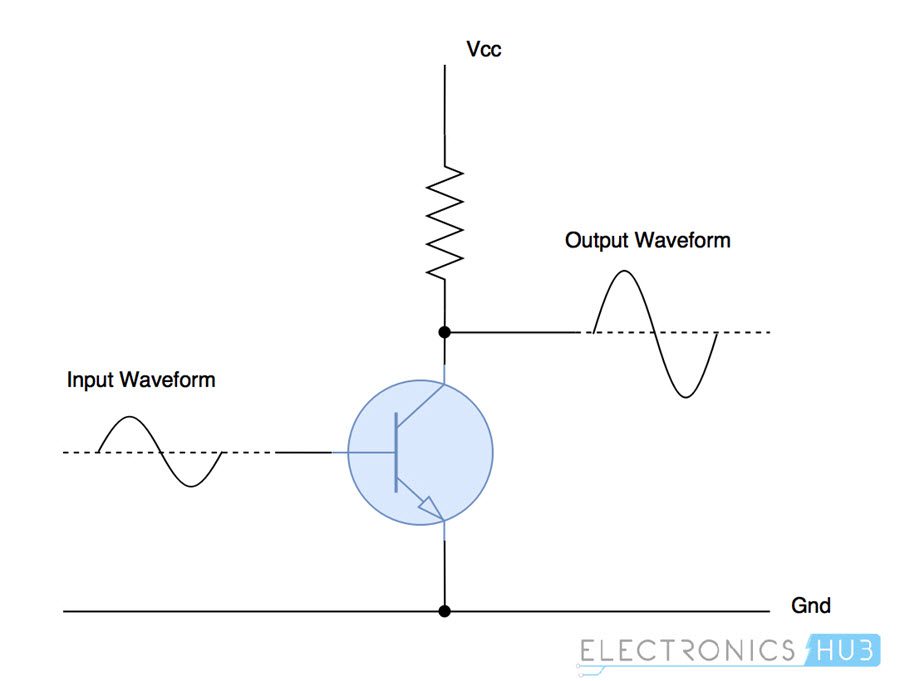
In this class of amplifiers, the active element (the electronic component used for amplifying, which is transistor in this case) is in use all the time even if there is no input signal. This generates lot of heat and reduces the efficiency of class A amplifiers to 25% in case of normal configuration and 50% in case of transformer coupled configuration.
The conduction angle (the portion of waveform used for amplification, out of 360°) for class A amplifiers is 360°. So, the signal distortion levels are very less allowing better high frequency performance.
Class B Power Amplifier
Class B power amplifiers are designed to reduce the efficiency and heating problems present in the class A amplifiers. Instead of a single transistor to amplify the entire waveform, this class of amplifiers use two complementary transistors.
One transistor amplifies the positive half of the waveform and the other amplifies the negative half of the waveform. So, each active device conducts for one half (180°) of the waveform and two of them, when combined, amplify the entire signal.
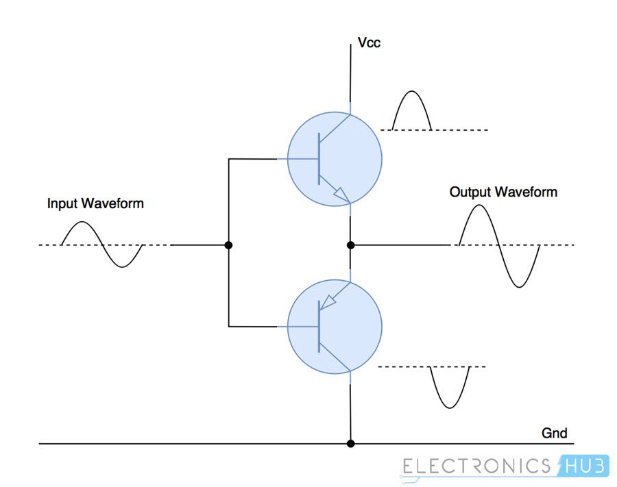
The efficiency of class B amplifiers is improved a lot over class A amplifiers because of two transistor design. They can reach a theoretical efficiency of about 75%. Power amplifiers of this class are used in battery operated devices like FM radios and transistor radios.
Because of superposition of two halves of the waveform, there exists a small distortion at the crossover region. To reduce this signal distortion, class AB amplifiers are designed.
Class AB Power Amplifier
Class AB amplifiers are a combination of class A and class B amplifiers. This class of amplifiers are designed to reduce the less efficiency problem of class A amplifiers and distortion of signal at crossover region in class B amplifiers.
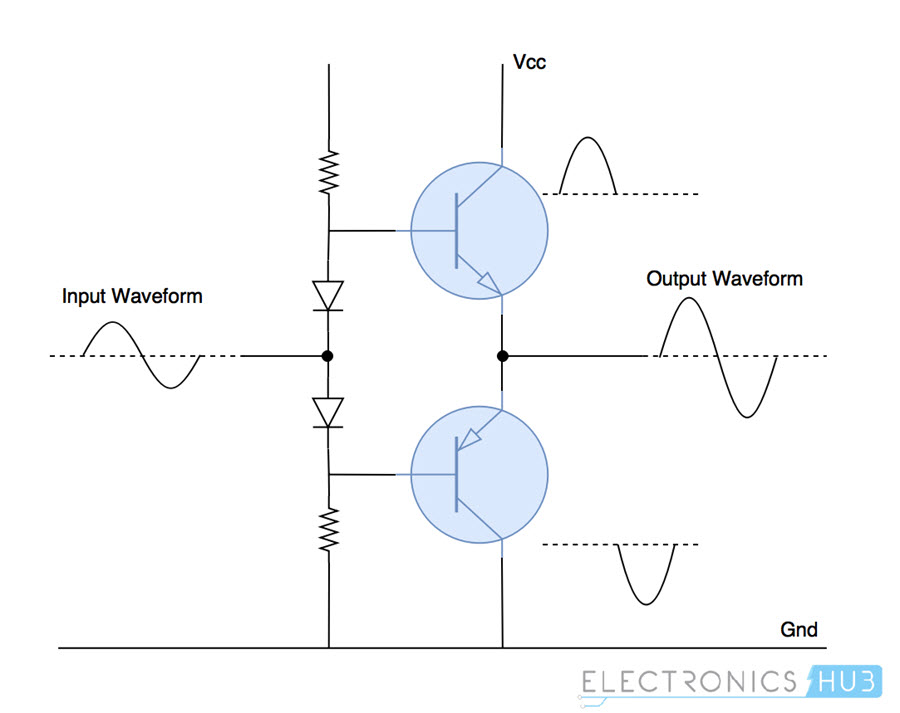
It maintains high frequency response like in class A amplifiers and good efficiency as in class B amplifiers. A combination of diodes and resistors are used to provide little bias voltage which reduces the distortion of waveform near the crossover region. There is a little drop in efficiency (60%) because of this.
Class C Power Amplifier
The design of class C power amplifiers allows greater efficiencies but reduces the linearity/conduction angle, which is under 90°. In other words, it sacrifices quality of amplification for increase in efficiency.
Lesser conduction angle implies greater distortion and so this class of amplifiers are not suited for audio amplification. They are used in high frequency oscillators and amplification of Radio Frequency signals.
Class C amplifiers generally contain a tuned load which filters and amplifies input signals of certain frequency, and the waveforms of other frequencies are suppressed.
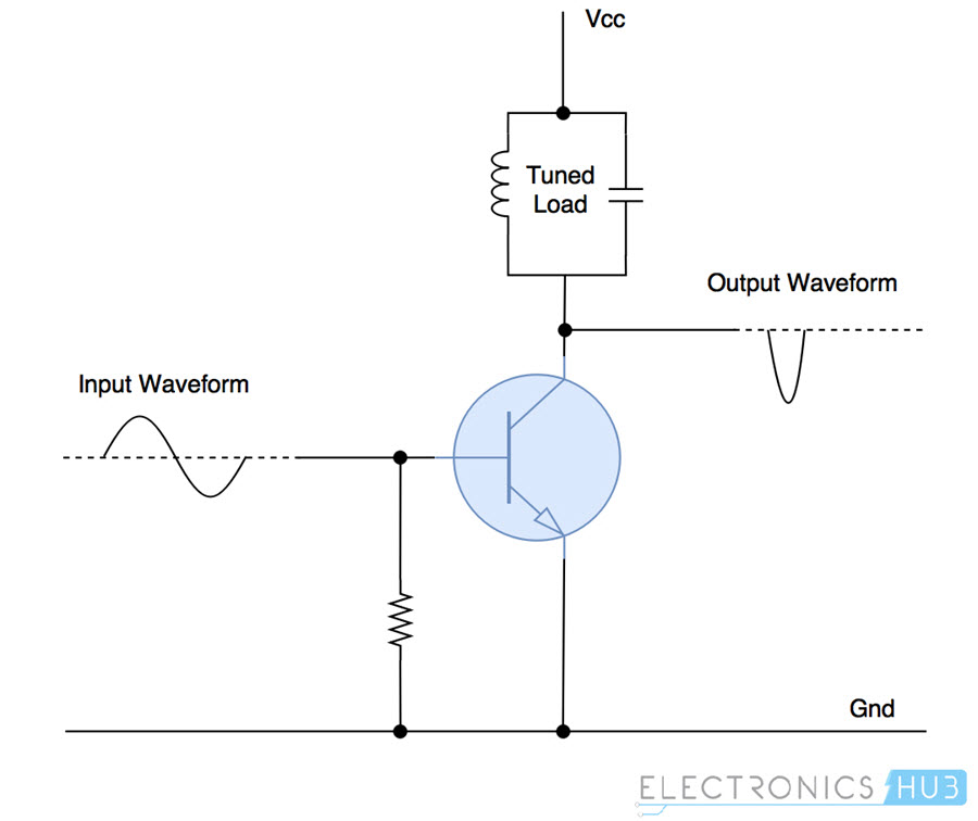
In this type of power amplifier, the active element conducts only when the input voltage is above a certain threshold, which reduces power dissipation and increases efficiency.
Class D Power Amplifier Classes:
Class D power amplifiers are highly efficient amplifiers that use pulse-width modulation (PWM) techniques to represent the analog signal. They are becoming increasingly popular due to their efficiency and compact size.
Class E Power Amplifiers:
Class E power amps are A variation of Class D amplifiers offering even higher efficiency but with more complex circuitry.
Class G and H Amplifiers:
These Class G and H power amplifiers are advanced amplifier classes that use multiple voltage rails or variable voltage supplies to improve efficiency over Class AB designs.
Power amplifier classes D, E, F, G etc. are used to amplify PWM modulated digital signals. They come under the category of switching power amplifiers and turn the output either constantly ON or constantly OFF without any other levels in between.
Because of this simplicity, power amplifiers falling under the above-mentioned classes can reach theoretical efficiencies of up to (90-100)%.
Power Amplifiers Applications
Below are the applications of power amplifiers across different sectors:
- Consumer Electronics: Audio power amplifiers are used in almost all consumer electronic devices ranging from microwave ovens, headphone drivers, televisions, mobile phones and Home theatre systems to theatrical and concert reinforcement systems.
- Industrial: Switching type power amplifiers are used for controlling most of the industrial actuator systems like servos and DC motors.
- Wireless Communication: High power amplifiers are important in transmission of cellular or FM broadcasting signals to users. Higher power levels made possible because of power amplifiers increases data transfer rates and usability. They are also used in satellite communication equipment.
A quick introduction to the concept of Power Amplifiers. You leaned what is a power amplifier and its need, different types and classes of power amplifiers and also couple of applications as well.
Related Posts:
- Current Amplifiers and Buffers
- Different Types and Applications of Amplifiers
- 100W MOSFET Power Amplifier Circuit
- Common Base Amplifier
- 200Watt Audio Amplifier
- Inverting Operational Amplifiers (Inverting Op-amp)
23 Responses
Hi very good tutorial . I have a question, could you please explain a little more about crossover region? Thank you
Very easy to understand from this web
very easy explanation..; Thankyou
Good and excellent explanation but kind help us convert it to PDF file
very easy explanation .thnkiv so mch
You have explained the topic very well keep it up
Thank you so much…the explanation is so easy to understand… Appreciate it
Amazing explanation but I want more explanation about q point in detail
This was very helpful and informative. Thank you so much for your service! All the best
Thanks for your evorts , you explained and cleared as a day
Thanks for the knowledge ..keep going
Thanks a lot. It really helped me with my project work
Could you make it into pdf please?? A nice tutorial ?
it’s very good for study’s paraphrase
Good work thank you ??
Good explanation
It’s very good for this explaination to the power amplifers that’s good for me becouse encourage my knowledge about it. Thanks alot.
good job…thank..
excellent work, thanks alot
niiccee tutorial . Explained it in a very simple wording
Very good explanation thanks
Very good explanation thanks for your excellent article
Very nice good explanation 👍
Leave a Reply Cancel reply
Your email address will not be published. Required fields are marked *
Get our Latest Newletters
Get great content that you love. No ads or spams, we promise.

How To Guides
Android Apple Windows Email YouTube Instagram SnapChat Gaming Discord Cloud Storage Google Sheets
Product Reviews
Home & Security Camera Motherboard PC & PC Accessories Laptops Speakers Car Accessories Air Conditioner Lawn & Garden Software Modem & Router
For Students
Electronics Projects Arduino Projects Embedded Free Circuits Mini Projects Robotics Sensor Cables & Wires RV Systems Solar
Interesting
Insights Tutorials Upcoming Sales Usernames Symbols Calculators Courses Deals Our Story
- Affiliate Disclosure
- Terms and Conditions
- Privacy Policy
Copyright © 2024 Electronicshub.org
- Trending Now
- Foundational Courses
- Data Science
- Practice Problem
- Machine Learning
- System Design
- DevOps Tutorial
Power Amplifier
Power amplifiers serve as fundamental electronic tools that enhance the strength of electrical signals, holding a pivotal position within numerous electronic systems. They fulfill crucial roles in applications necessitating signal augmentation, such as audio systems, RF (Radio Frequency) transmitters, and various other domains. In this all-encompassing exposition, we will explore the domain of power amplifiers, examining their classifications, operational categories, utility scenarios, and attributes related to performances.
Table of Content
- Comparison of Different Classes
- Voltage Vs Power Amplifiers
- Solved Examples
- Advantages and Disadvantages
- Applications
What is a Power Amplifier ?
An electronic circuit exists that enhances the strength of an incoming signal, referred to as a power amplifier. In contrast to small-signal amplifiers, which concentrate on boosting voltage or current while preserving smoothness, power amplifiers are engineered to deliver robust output with minimal aberration. They find extensive utility in situations demanding a substantial augmentation of signal potency, such as managing audio system speakers or transmitting wireless signals over extended distances.
.png)
Block Diagram of Power Amplifier
The main features of these types of amplifiers are circuit power η, the maximum amount of power that the circuit can handle, and impedance matching to the output device. Power amplifiers are designed with BJT and normal CE mode is used in power amplifiers.
Amplifier Efficiency: It is defined as the ratio of output AC power to the input DC power. [Tex]η= \frac{P_{ac}}{P_{dc}}*100% [/Tex] Distortion: The change in output wave shape from the input wave shape of an amplifier is known as distortion. The distortion can be reduced by using negative feedback in the amplifier.
What are the Types of Power Amplifier?
Power amplifiers can also be classified based on various factors. Let’s explore some common classifications:
Classification Based on Frequencies
- Audio Power Amplifiers : It is designed for amplifying audio signals. These amplifiers are commonly used in speakers, televisions, and mobile phones, etc, to increase the power of weak audio signal. It ranges from few milliwatts to thousands of watts.
- Radio Frequency Power Amplifiers: It is used in radio frequency applications. The range of wireless transmissions, which rely on antennas to send modulated waves over large distances, is influenced by the signal strength. Antennas need input signals that are thousands of kilowatts in power to broadcast FM. Power amplifiers are used to boost the power so that the modulated waves go to the necessary distance.
- DC Power Amplifiers: DC power amplifiers amplify PWM signals in electronic control systems for high-power motors or actuators. They increase input power from microcontrollers and send amplified signals to DC motors or actuators, ensuring they are driven effectively.
Classification Based on Mode of Operation
.png)
Graphs of Classes of Power Amplifier
We will study about classes of power amplifier in the next topic.
Classes of Power Amplifiers
Power amplifiers can be categorized into several classes based on their mode of operation and efficiency. Classes of power amplifiers are as follows:
Class A Power Amplifier
Transformer coupled class a power amplifier, push-pull class a power amplifier, class b power amplifier, class ab power amplifier, class c power amplifier.
Class A amplifiers operate in a mode where the output transistors conduct during the entire cycle of the input signal. This results in minimal distortion, but also low efficiency, since the transistors are always conducting, leading to significant heat generation.
.png)
Circuit Diagram (Class A Power Amplifier)
- With class A amplifier Q point lies middle of the load line so that signal can swing over the maximum possible range without saturating or cut off the transistor as seen in the figure below.
- Due to this, the output signal is obtained for the full cycle of the AC input. i.e. 360 o .
- Due to changes in Ic, the voltage Vce will also fluctuate sinusoidally.
- The operating point (Q-point) of the power transistor is biased to be roughly in the middle of the load line.
.png)
Graphical Representation (Class A Power Amplifier)
Important Mathematical Equations of Power Amplifier
DC power drawn from collector battery: [Tex]P_{in} = V*I [/Tex] [Tex]P_{in} = V_{cc}*(I_{c})_{Q} [/Tex] AC power output which is developed across the load resistor: [Tex](P_{out})_{ac} = I^2R_{c} [/Tex] [Tex](P_{out})_{ac} = \frac{V^2}{R_{c}} = (\frac{V_{m}}{\sqrt{2}})^2*\frac{1}{R_{c}} [/Tex] [Tex](P_{out})_{ac} = \frac{V_{m}^2}{2R_{c}} [/Tex]
Transformer coupled Class A amplifiers use transformers to couple the input and output stages, providing isolation and impedance matching. This configuration can offer excellent linearity and power gain.

Circuit Diagram (Transformer Coupled Class A Amplifiers)
Due to the transformer primary coil’s extremely low resistance, there is less dc power loss. The relationship between the primary and secondary values of voltage, current and impedance are summarized as:
[Tex]\frac{N1}{N2} = \frac{V1}{V2} = \frac{I2}{I1} [/Tex] [Tex](\frac{N1}{N2})^2 = \frac{Z1}{Z2} = \frac{Z1}{Rl} [/Tex] N1, N2 = the number of turns in the primary and secondary V1, V2 = the primary and secondary voltages I1, I2 = the primary and secondary currents Z1, Z2 = the primary and secondary impedance ( Z2 = Rl )
- Principle advantage: Lower distortion than Class C, B & AB. And it is simple to construct.
- Principle disadvantage: Lower power efficiency than Class C, B & AB and large power dissipation in the power transistors.
The push-pull Class A amplifier overcomes the efficiency limitations of pure Class A amplifiers by using a pair of transistors in a push-pull configuration. This design allows one transistor to be on while the other is off, reducing heat generation and improving efficiency.

Circuit Diagram ( Push-Pull Class A Amplifier)
The biasing of the transistor in class B operation is in such a way that at zero signal condition, there will be no collector current. The operating point is selected to be at collector cut off voltage. So, when the signal is applied, only the positive half cycle is amplified at the output.

Circuit Diagram (Class B Power Amplifier)
- The collector current only flows for 180 degrees because the transistor only operates for one-half of the input cycle, as depicted in the below picture.
- In order to achieve this, the Q point is changed to be a cut-off, or on the X-axis, as indicated in the picture below. As a result, the transistor remains in the off state in the absence of an ac input signal.
- (Vcc, 0) are the Q-point’s coordinates.

Graphical Representation (Class B Power Amplifier)
Operation of Class-B Power Amplifier
- The B-E junction of the transistor is only forward-biased during the positive half cycle of the input. When a sinusoidal input signal is applied to the transistor’s base, base current to begin flowing.
- Utilizing two transistors to generate the output signal’s full cycle on alternate half cycles of the input signal, it will remove the distortion. There is only 180° of conductivity for each transistor. The push-pull class B power amplifier is known as the same.
As the name states, AB amplifiers are a combination of class A and class B amplifier. Class AB amplifier not only solve the reduced efficiency issue of class A, but also solves crossover distortion issue that present in class B amplifier.

Circuit Diagram (Class AB Power Amplifier)
To obtain the output signal for an AC input signal that is angled between 180 and 360 degrees. The Q point is situated just below the midpoint of the load line and slightly above the X-axis.
In contrast to class A and class B operations, the Q point is neither on the X-axis nor in the middle of the load line. Between the two, it lies. Hence, the operation is known as class AB. The transistor conducts for more than 180° (class B) but less than 360° (class A), so its power dissipation is greater in class B operation than in class A operation.
When the collector current flows for less than half cycle of the input signal, the power amplifier is known as class C power amplifier. The efficiency of class C amplifier is high while linearity is poor. The conduction angle for class C is less than 180 o . It is generally around 90 o , which means the transistor remains idle for more than half of the input signal. So, the output current will be delivered for less time compared to the application of the input signal.

Circuit Diagram (Class C Power Amplifier)
- This design of power has even greater efficiencies than class B amplifiers but sacrifices the quality of amplification.
- For this, the operating point is modified to be below the X-axis as shown in figure below. As a result, the transistor is biased below the cut-off.

Graphical Representation (Class C Power Amplifier)
Operation of Class C Power Amplifier
- The transistor can stay in the active region for less than a half-cycle period because of the biasing below the cut-off. Thus, the collector current flows for a shorter angle than 180°. Conduction angle is therefore less than 180 degrees.
- The output signal is severely distorted because of the smaller conduction angle. Contrary to a class B power amplifier, the % distortion is larger.
- The efficiency is often greater than 95%.
Comparison of Different Classes of Power Amplifiers
The comparison of different classes of power amplifier on the basis of efficiency, linearity, distortion and applications are given below:
|
|
|
|
|
|---|---|---|---|---|
Class A | Low | Excellent | Minimal | High-fidelity audio |
Push-Pull Class A | Moderate | Good | Moderate | RF transmitters |
Transformer Coupled Class A | Moderate | Excellent | Minimal | Audio amplification |
Class B | Moderate | Good | Moderate to High | Motor control, power inverters |
Class AB | Moderate | Good | Moderate | Audio amplification, car audio |
Class C | High | Poor | High | RF signal amplification, broadcasting |
Class D | High | Good | Low | Portable audio devices, power-efficient applications |
Class E | High | Good | Low | Wireless communication (RFID, NFC) |
Comparison between Voltage and Power Amplifiers
|
|
|
|---|---|---|
Objective | Increase voltage of input signal | Increase power of input signal |
Mode of Operation | Linear | Non-linear |
Efficiency | High | Moderate to low |
Distortion | Minimal | Can have higher distortion |
Typical Applications | Small-signal amplification | High-power applications |
Amplification Range | Low to moderate | High |
Solved Examples of Power Amplifier
There are some Solved Examples of Power Amplifier given below :
1. Calculate the efficiency of a Class A power amplifier with an output power of 10 watts and a DC power input of 20 watts.
[Tex]Efficiency = \frac{Output Power }{ DC Input Power}*100% [/Tex]
[Tex]Efficiency = \frac{10}{ 20}*100 = 50% [/Tex]
2. Determine the gain of a transformer-coupled Class A amplifier with a turns ratio of 1:5.
[Tex]Gain = \frac{Number of Turns in Secondary}{Number of Turns in Primary} [/Tex]
Advantages and Disadvantages of Power Amplifiers
There are some list of Advantages and Disadvantages of Power Amplifiers given below :
Advantages of Power Amplifiers
- Signal Amplification: It enhances the strength of an incoming signal making it suitable for operating the devices like speakers for delivering of high-quality and clean signal.
- Enhancing the audio quality: Power amplifiers helps in improving the sound quality of the system. This is achieved due to the less distortion and high linearity of the system. For eg. Class A and Class AB Power Amplifier are suitable for improving the sound quality.
- Efficiency: Power amplifiers reduces the power loss and hence improving the efficiency. In case of Class B Power Amplifier, there is no power loss under quiescent circumstances.
- Wide Range of Applications: It finds its use in diverse applications like audio amplification, RF signal transmission, consumer electronics, telecommunications, and industrial sectors, etc.
- Customizability: There are various classes of Power Amplifier available. Each classes has its own specification. This helps the designers to develop the configurations according to the system need.
Disadvantages of Power Amplifiers
- Heat Generation: Power amplifiers generates the heat while working. Hence, cooling systems are used for the prevention of overheating. It leads to the increase in the cost of the device.
- Size and Weight: The high power application Power amplifiers are large and heavy. So, it can’t be used in the portable or small sized devices.
- Non-Linear Distortion: When the transistor change its states from ON to OFF and vice versa, some distortion signals are generated. This leads to the non-linearity of the systems. For example in Class B Power Amplifier, crossover distortion is present in the output waveform. In class C, output waveform is distorted.
- Complex Design: High-power amplifiers often require complex designs and precise component matching, making them challenging and costly to manufacture.
Applications of Power Amplifiers
- Audio Systems: Driving speakers in home theaters and concert venues.
- Wireless Communications: It helps in transmitting RF signals in cell towers and satellite communication. Higher power levels made possible because of power amplifiers increases data transfer rates and usability.
- Radar Systems: In the radar systems it amplifies radar signals for accurate object detection.
- Industrial: It is used in servo motor and DC motor. Switching type power amplifiers are used for controlling most of the industrial actuator systems. It is helpful in controlling motors and actuators in manufacturing processes.
- Medical Equipment: Powering ultrasound and MRI systems.
In this article we have studied about Power Amplifier, classification and different classes. It is the fundamental electronic tools that enhance the strength of electrical signals. It finds its application in various fields like audio systems, RF transmitters, and many more is playing a important role in the technology driven world.
FAQs on Power Amplifier
What is the gain of power amplifier.
Gain of he Power Amplifier is the ratio of output power and input power. It is measured in dB. The mathematical formula for gain is [Tex]10 * log_{10}(\frac{Pout}{Pin}) [/Tex]
Why biasing in the power amplifier important?
In order to minimize the distortion, making the system linear and enhancing the performance of the amplifier, biasing is important.
How load impedance and efficiency of Power Amplifier are related to each other?
When the load impedance matches with the output impedance of the power amplifier, efficiency will be the highest.
Please Login to comment...
Similar reads.
- Geeks Premier League
- Power Electronics
- Geeks Premier League 2023
Improve your Coding Skills with Practice
What kind of Experience do you want to share?

Power Amplifier: Types, Classifications, and Applications
What is an amplifier?
An amplifier is a device used to increase an input signal’s voltage, current, or power.
A weak electrical signal is taken in and converted into a stronger output signal. External power is used to cause this change.
There are three main classifications of amplifiers depending on the changes it makes to the input signal: voltage, current, or power amplifier.
Power Amplifier
Power amplifiers are used to increase the power level of a signal. A low-power signal is converted to a higher-power signal to drive output devices
The most common example is an audio amplifier, which drives headphones and loudspeakers.
The position of a power amplifier is usually at the end of the chain of amplifiers and other devices, as it is designed to drive output devices directly.

Audio Amplifier Block Diagram
The power amplifier requires the input signal to be at a certain magnitude (signals from the microphone aren’t strong enough for the power amplifier in this case).
Therefore, voltage or current amplifiers are used to pre-amplify the raw audio signals from the input device by increasing voltage or current.
After modifications are made by the pre-amplifiers, the signal is sent through the volume control block which makes adjustments to the audio signal
Lastly, the signal is sent as input through the power amplifier which is sent as output to the speaker.
This output power is AC , whereas the power fed to the amplifier is DC.
Therefore, it can be said that a power amplifier works by converting DC power to AC power.
Power Amplifier Types
Power amplifiers are divided into three types:
1) Audio Power Amplifiers
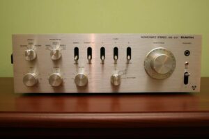
These amplifiers are used commonly in speakers, televisions, mobile phones, etc.
An audio power amplifier can produce anywhere from a few milliwatts (such as in headphone amplifiers) to hundreds of watts (such as in Hi-Fi/Home theater systems).
2) Direct-Coupled (DC) Power Amplifiers
DC power amplifiers amplify the power of PWM (Pulse-Width Modulated) signals.
Electronic control systems, which require high power signals in order to drive actuators or motors, use DC power amplifiers.
Amplified signals are sent to DC motors and actuators after they are accepted as non-amplified signals from microcontroller inputs.
3) Radio Frequency Power Amplifiers
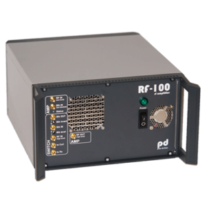
For wireless transmissions to work, modulated waves must be transmitted across great distances in air.
The range of transmission is dependent on the strength of the signals given to the antenna when the signals are broadcast via antennas.
The antennas in wireless transmissions such as FM broadcasting require input signals with power of thousands of kilowatts.
In such systems, power amplifiers give the required boost to the modulated waves in order to provide sufficient power to cover the large transmission distance.
Power Amplifier Classes
The operation and output characteristics of a power amplifier are dependent on its circuit design.
Therefore, a power amplifier is classified according to its circuit configuration.
Power amplifier classes are differentiated based on their method of operation by using letter symbols such as A, B, C, etc.
Two main categories of classification are based on the type of signals that are amplified:
- Power amplifiers that amplify analog signals fall under categories A, B, AB, or C.
- Power amplifiers that amplify digital (or PWM) signals fall under categories D, E, F, and so on.
However, classes A, B, AB, and C are the most commonly used amplifiers (used in audio amplifiers).
Class A Power Amplifier
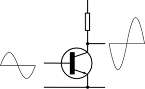
Class A amplifiers are the most commonly used class of power amplifiers but are superseded by more efficient and better designs.
Positive and negative halves make up analog waveforms. The full input waveform is utilized in the amplification process in class A amplifiers.
A class A power amplifier uses a single transistor and both the positive and negative halves of the waveforms are amplified by it, leading to a simple design.
The active element—the transistor in this case which serves as the amplifier— remains conducting at all times, even if there is no input signal.
Therefore, class A amplifiers have a reduced efficiency as the transistor generates a lot of heat. The theoretical maximum efficiency that can be achieved is 25% only in usual settings, and 50% in a transformer or inductively coupled configuration.
The conduction angle, which is the part of the waveform used for amplification out of 360°, is 360°.
This means that there is a better high frequency performance due to lower levels of signal distortion.
Class B Power Amplifier

Each half of the waveform is amplified by a single transistor instead of both halves being amplified by a single transistor.
Due to two transistors in this design, the heating problems that were present in class A amplifiers are reduced in class B amplifiers and therefore the efficiency is increased.
The maximum efficiency achievable is ≈ 78.5%.
Each active element conducts for half of the waveform, making the conduction angle 180°, and both active elements combined make it a complete waveform.
Class B power amplifiers are used in battery-powered devices such as FM radios and transistor radios.
The only problem with this class of amplifiers is that there is a tiny distortion in the cross-over region where the halves of the waveform “join”. This is known as crossover distortion.
Therefore, class AB is designed to resolve this issue.
Class AB Power Amplifier

Class AB power amplifier not only solves the reduced efficiency issue of class A, but also solves crossover distortion that is present in class B amplifiers.
The efficiency issue is resolved by using two transistors just like in class B.
While the crossover distortion problem is resolved by the use of diodes and resistors that provide a bias voltage so that the device is never completely off when not in use.
Negative feedback can also be used to further reduce distortion.
However, due to this, there is a slight reduction in the efficiency of class AB amplifiers as compared to class B amplifiers, but they are still more efficient than class A amplifiers.
The maximum efficiency is about 60% in class AB amplifiers.
Class C Power Amplifier
This design of power amplifiers has even greater efficiencies than class B amplifiers but sacrifices the quality of amplification.
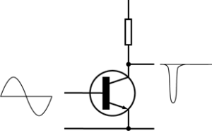
The class C power amplifier (untuned version)
The conduction angle is reduced to less than 90°, resulting in greater distortion.
Application of class C amplifiers is therefore limited to RF transmitters and high-frequency oscillators.
Class C amplifiers have two modes of operation which are tuned and untuned, but generally, the tuned mode is used.
A tuned load is present which filters and amplifies input signals of a certain frequency while keeping other frequency waveforms suppressed.
Power dissipation is reduced and efficiency is increased because the active element only conducts when the voltage is above a certain threshold.
Classes D, E, F, etc. Power Amplifiers
Classes beyond class D are designed to amplify PWM digital signals.
Each device’s conduction angle now varies depending on the pulse width rather than being directly tied to the input signal.
The transistors function as electronic switches rather than gain devices in class D amplifiers, they are either off or on.
These power amplifiers are simple due to the on or off functionality, and therefore have high theoretical efficiencies that reach up to 90%-100%.

Block Diagram of Class D Power Amplifier
Power Amplifiers Applications
Power amplifiers are used in different sectors for various functions:
Consumer/Home Electronics
Almost all consumer and home electronic devices use audio power amplifiers.
Examples include devices ranging from microwave ovens, televisions, mobile phones, all the way to home theatre systems and concert equipment etc.
Wireless Communication
Transmission of cellular or FM broadcasting signals require high power amplifiers.
Power amplifiers increase rates of data transfer by using high power levels.
Satellite communication equipment also uses power amplifiers.
Industrial Equipment
Most industrial actuator systems such as DC motors and servos use class D type power amplifiers.
Sharing is caring:
- Share on Tumblr

Discover more from Electrical Engineering 123
Subscribe to get the latest posts sent to your email.
Type your email…
Subscribe now to keep reading and get access to the full archive.
Continue reading
Continue to site >>>

About | Contact | Advertise
Classes of Power Amplifiers
In electronics, Amplifier is the most commonly used circuit device with huge application possibilities. In Audio related electronics pre-amplifier and power amplifiers are two different types of amplifier systems which are used for sound amplification related purposes. But, other than this application-specific purpose, there are huge differences in various types of amplifiers, mainly in Power Amplifiers. So here we will explore different classes of amplifiers along with their advantages and disadvantages.
Classifications of Amplifiers using Letters
Amplifier classes are the identity of amplifier’s performance and characteristics. Different type of power amplifiers gives different responses when passing current through them. According to their specifications, Amplifiers are assigned different letter or alphabets which represent their classes. There are different classes of amplifiers starting from A, B, C, AB, D, E, F, T etc . Out of those classes most commonly used audio amplifiers classes are A, B, AB, C. Other Classes are modern amplifiers which use switching topologies and PWM (Pulse Width Modulation) technique to drive the output load. Sometimes, improved version of traditional classes are assigned a letter to classify them as a different class of amplifier, like class G amplifier is a modified Amplifier class of Class B or Class AB amplifier.
Classes of the amplifier represent the input cycle proportion when the current is passed through amplifier. The input cycle is the conduction angle derives from the sinusoidal wave conduction in the amplifier input. This conducting angle is highly proportional with the Amplifiers on time during a full cycle. If the amplifier is always ON during a cycle, the conduction angle will be 360 degrees . So, if an amplifier provides 360-degree conduction angle, then the amplifier used complete input signal and the active element conducted through the 100% time period of a complete sinusoidal cycle.
Below, we will demonstrate traditional Power amplifier classes ranging from Class A, B, AB and C, and also demonstrate Class D amplifier which is widely used in switching designs. These classes are not only used in Power Amplifier but also used in Audio Amplifiers circuits .
Class A Amplifier
Class A amplifier is a high gain amplifier with high linearity. In case of Class A amplifier, the conduction angle is 360 degree. As we stated above, a 360-degree conduction angle means the amplifier device remains active for the entire time and use complete input signal. In the below image an ideal class A amplifier is shown.
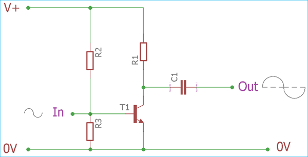
As we can see in the image, there is one active element, a transistor. The bias of the transistor remains ON all of the time. Due to this never turn off feature, Class A amplifier provides better high frequency and feedback loop stability . Other than these advantages, Class A amplifier is easy to construct with a single-device component and minimum parts count.
Despite the advantages and high linearity, certainly, it has many limitations. Due to continuous conducting nature, the class A amplifier introduce high power loss . Also, due to high linearity, Class A amplifier provides distortion and noises. The power supply and the bias construction need careful component selection to avoid unwanted noise and to minimize the distortion.
Because of high power loss in Class A amplifier, it emits heat and requires higher heat sink space. The efficiency is very poor in Class A amplifiers, theoretically, the efficiency varies between 25 to 30 % if used with the usual configuration. The efficiency can be improved using inductively coupled configuration but the efficiency in such case is not more than 45-50%, thus it is only suitable for low signal or low power level amplification purposes.
Class B Amplifier
The Class B amplifier is a bit different from the Class A. It is created using two active devices which conduct half of the actual cycle , ie 180 degrees of the cycle. Two devices provide combined current drive for the load.
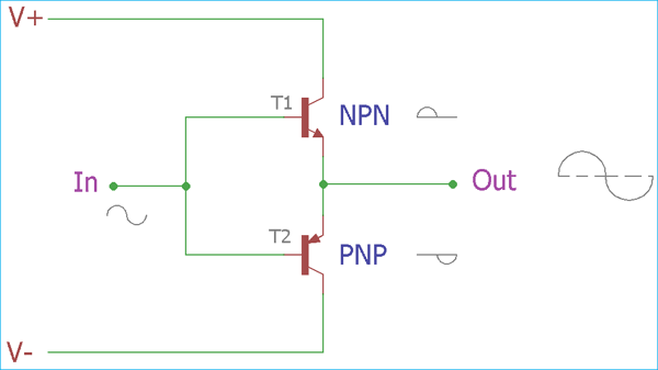
In the above image, an Ideal Class B amplifier configuration has been shown. It consists two active devices which get biased one by one during the positive and negative half cycle of sinusoidal wave and thus the signal gets pushed or pulled to the amplified level from both positive and negative side and combine the result we get complete cycle across the output. Each device turned on or became active half of the cycle, and due to this the efficiency gets improved, comparing to 25- 30% efficiency of Class A amplifier, it provides more than 60% efficiency theoretically. We can see each device input and output signal graph in the below image. The efficiency is not more than 78% for Class B amplifier . The heat dissipation is minimized in this class providing a low heat sink space .
But, this class also have limitation. A very profound limitation of this class is the crossover distortion . As two devices provides each half of the sinusoidal waves which are combined and joined across the output, there is a mismatch (cross over) in the region, where two halves are combined. This is because when one device complete the half cycle, the other one needs to provide the same power almost at the same time when other one finish the job. It is difficult to fix this error in class A amplifier as during the active device the other device remains completely inactive. The error provides a distortion in the output signal. Due to this limitation, it is a major fail for precision audio amplifier application.
Class AB Amplifier
An alternate approach to overcome the cross-over distortion, is to use the AB amplifier . Class AB amplifier uses intermediate conduction angle of both Classes A and B, thus we can see the property of both Class A and Class B amplifier in this AB class of amplifier topology. Same as class B, it has the same configuration with two active devices which conducts during half of the cycles individually but each device biased differently so they do not get completely OFF during the unusable moment (crossover moment). Each device does not leave the conduction immediately after completing the half of the sinusoidal waveform, instead they conduct a small amount of input on another half cycle. Using this biasing technique, the crossover mismatch during the dead zone is dramatically reduced.
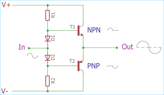
But in this configuration, efficiency is reduced as the linearity of the devices is compromised. The efficiency remains more than the efficiency of typical Class A amplifier but it is less than the Class B amplifier system. Also, the diodes need to be carefully chosen with the exact same rating and need to be placed as close as possible to the output device. In some circuit construction, designers tend to add small value resistor to provide stable quiescent current across the device to minimize the distortion across the output.
Class C Amplifier
Apart from the Class A, B, and AB amplifier, there is another amplifier Class C. It’s a traditional amplifier which works differently than the other amplifiers classes. Class C amplifier is tuned amplifier which works in two different operating modes, tuned or untuned. The efficiency of Class C amplifier is much more than the A, B, and AB. Maximum 80% efficiency can be achieved in radio frequency related operations
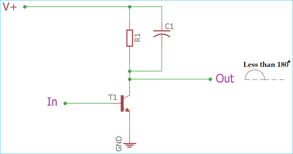
Class C amplifier uses less than 180-degree conduction angle. During the untuned mode, the tuner section is omitted from the amplifier configuration. In this operation, Class C amplifier also gives huge distortion across the output.
When the circuit is exposed to a tuned load, the circuit clamps the output bias level with the average output voltage equal to the supply voltage. The tuned operation is called as clamper . During this operation, the signal gets its proper shape and the center frequency became less distorted.
In typical uses, Class C amplifier gives 60-70% efficiency.
Class D Amplifier
Class D amplifier is a switching amplifier which uses Pulse Width Modulation or PWM. The conduction angle is not a factor in such case as the direct input signal is changed with a variable pulse width.
In this Class D amplifier system, the linear gain is not accepted as they work just like a typical switch which have only two operations, ON or OFF.

Before processing the input signal, the analog signal is converted into a pulse stream by various modulation techniques and then it is applied to the amplifier system. As the pulses duration is related with the analog signal it is again reconstructed using low pass filter across the output.
Class D amplifier is the highest power efficient amplifier class in the A, B, AB, and C and D segment. It has smaller heat dissipation, so small heatsink is needed. The circuit requires various switching components like MOSFETs which has low on resistance.
It is a widely used topology in digital audio players or controlling the motors as well. But we should keep in mind that It is not a Digital converter. Although, for higher frequency, Class D amplifier is not a perfect choice as it has bandwidth limitations in few cases depending on the low pass filter and converter module capabilities.
Other Amplifier Classes
Other than the Traditional amplifiers, there are few more classes, which are class E, Class F, Class G, and H.
Class E amplifier is a highly efficient power amplifier which uses switching topologies and works in radio frequencies. A single pole switching element and the tuned reactive network is the main component to use with the class E amplifier.
Class F is high impedance amplifier in respect of the harmonics. It can be driven using square wave or sine wave. For the sinusoidal wave input, this amplifier can be tuned using an inductor and can be used to increase the gain.
Class G use rail switching to decrease the power consumption and to improve efficiency performance. And Class H is the further improved version of Class G.
Additional classes are special purpose amplifier. In some cases, the letters are provided by the manufacturer for signifying their proprietary design. One best example is Class T amplifier which is a trademark for a special type of switching Class D amplifier, used for Tripath’s amplifier technologies which is a patented design.
Ask Our Community Members

Great analysis
- Log in or register to post comments

Join 100K+ Subscribers
Your email is safe with us, we don’t spam.
Be a part of our ever growing community.
Copyright © 2023 Circuit Digest . All rights reserved.
WatElectronics.com
Power Amplifier Circuit Diagram, Types and Applications
October 26, 2019 By WatElectronics
Basics of Power Amplifier
Power amplifier are the basic category of amplifiers which is used to amplify the power of the input signal which may be either a digital signal or an analog signal from few milli watts to several milli watts depending on the need of amplification. These types of amplifiers are found in almost every analog to digital devices sorrounding us. From radio tuners to microwave to laptops to cell phones use power amplifiers in some form or the other.
What is a Power Amplifier?
The amplifier that has the property of converting the applied DC power that comes from the supply into AC power so that the load is provided with the sufficient amount of power, these types of amplifiers are defined as power amplifiers. In this case of amplifiers, the magnitude of the applied power tends to increase. Hence these amplifiers are used in various applications where the power requirement is to drive the load.
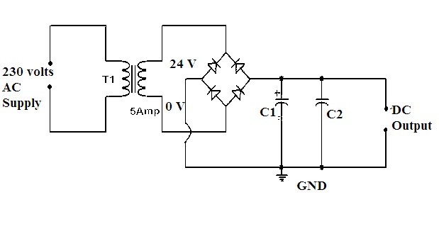
Power Amplifier Circuit Diagram
The amplifiers are classified based on the applied signals either it is the voltage signal or the power signal. This can be done based on the obtained characteristics of the input values and the output values. The type of devices that are connected to the amplifiers results in its classification as
1. Audio Power Amplifiers
The amplifiers where the amplification is required to amplify the audio signals are known as audio power amplifiers. In the headphones, transmitters, radio devices etc… these amplifiers are utilized. For example, the signal is of milliwatts after amplification it has the capacity of converting it into thousands of watts.
2. Radio Frequency Power Amplifiers
This type of amplifier is used frequently in long distances transmissions, that is the transmission over wireless media. The transmission of such signals requires amplification so that the strength of the signals can be improved and the data can be transmitted to long distances. These amplifiers are most widely used for the FM signals broadcasting.
3. DC Power Amplifiers
These amplifiers are used to amplify the Pulse Width Modulated signals. In this width of the pulse is modulated so that logic signals can be given to the motors to work based on it. The input will be taken from micro-controller units and the power of it will be increased and provides the amplified signals to the motors of DC type.
Classes of Power Amplifier
In multiple ways, the circuit of the power amplifier can be designed. Each circuit design possesses different characteristics as well as it produces various outputs. So to differentiate these amplifiers the classification is done in the alphabetical order.
The input signals that needs to be amplified can be either an analog signal or a digital signal. Based on that the power amplifer is classified as ClassA, B, AB or C and D, E, F,T etc… . For Analog signals either ClassA, ClassB, ClassAB, ClassC power amplifier are used. For digital signals ClassD,ClassE, ClassF power amplifiers are used.
1. Class A:
In this class of amplification, the signals of alternating current that consists of both positive and the negative halves are amplified by the single transistor in the circuit. Hence the construction of the class A circuit is simple in design. Because of this reason these amplifiers are the most frequently used one.

Class A Power Amplifier Circuit
The drawback of this circuit is that the transistor present in this circuit remains always on as it conducts in both positive and negative cycle of the input signal. Since the transistor is active for both the half cycles it dissipates lots of heat and this results in the decrease in the overall efficiency of the circuit. It also requires a heat sink to absorb the heat dissipated by the circuit. The angle of conduction for this class of amplifier is considered to be 360 degrees. The distortion in this type of amplifier is said to be minimum which results in better performance.
To overcome the drawback of the unnecessary heating of the device class B circuit of the power amplifier was designed. Rather than using the single transistor, in this circuit it is designed with the help of the two transistors( one NPN and other PNP) that complement each other.
The angle of conduction for these kinds of class amplifiers is 180 degrees. Therefore one half of the cycle that is positive cycle is amplified by one transistor and the remaining half that is the negative cycle is amplified by the second transistor. The corresponding transistor gets ON when the respective halves are amplified and thereby the overall signal gets amplified.

Class B Power Amplifier Circuit
In this way, the efficiency compared to the class A amplifier is improved to 70 percent (theoretically). These are mostly preferred for the devices that operate with the help of batteries. But here the two transistors follow superposition that leads to the distortion over the cross-region. These kinds of distortions was taken care in the design of class AB amplifiers .
This class of amplifiers possesses greater efficiencies but the design gets compromised because it goes through severe distortions. The greater efficiencies but the lesser are the conduction angle that is up to 90 degrees.

Class C Power Amplifier Circuit
As the signal generated from this circuit is of maximum distortion it cannot be preferred for the amplification of the audio signals. It is preferred in the oscillators that have frequency consisting high in range. It consists of the tuning load through which the input signals are filtered and amplified. Other than the considered frequency rest of the frequency signals are suppressed. This type is used for frequency modulation of the signals which are required for FM transmissions.
In this way, the various classes of the amplifiers are designed and discussed. There are other classes such as class D, Class E, class F, etc… where the pulse width modulated signals are amplified. These classes are generally preferred during switching applications or digital logic operations.
Applications:
There are wide varieties of applications of these amplifiers in the various sectors.
• These are used in varieties of devices such as headphones, microwave ovens, home theater systems, etc… these are the most important part of the basic electronics that comes under the category of the consumer’s range and household needs.
• To control servo motors and the specific DC motors the power amplifiers are utilized.
• As the wireless transmission requires high-frequency range for the transmission of the signals over a long distance the power amplification is beneficial in such cases. Higher the levels of power higher the transfer rate of data and its usability.
• It is also utilized in the types of equipment designed for the communication of the satellites.
Please refer to this link to know more about Regulated DC Power Supply MCQ’s & Transistor Audio Power Amplifiers MCQs
Please refer to this link to know more Power Amplifier MCQs
Hence the above are some of the applications of power amplifiers in the various fields.
Now after discussing all the basic things that relate to power amplifiers can you describe the design criteria of class AB amplifiers ?

- My presentations
Auth with social network:
Download presentation
We think you have liked this presentation. If you wish to download it, please recommend it to your friends in any social system. Share buttons are a little bit lower. Thank you!
Presentation is loading. Please wait.
Power Amplifiers.
Published by Οἰνεύς Πρωτονοτάριος Modified over 4 years ago
Similar presentations
Presentation on theme: "Power Amplifiers."— Presentation transcript:

Chapter 12 Power Amplifiers

Kazi Md. Shahiduzzaman Lecturer, EEE,NUB

Lecture 8 Power Amplifier (Class A)

Output Stages and Power Amplifiers Output stage delivers the output signal to the load without loss of gain due to Low output resistance D.S.P. Filter.

Class AB - Protection A short circuit output causes the current demand to rise beyond the design limit. In practice, it rises just far enough to destroy.

Power Electronics Introduction Bipolar Transistor Power Amplifiers

McGraw-Hill © 2008 The McGraw-Hill Companies Inc. All rights reserved. Electronics Principles & Applications Seventh Edition Chapter 8 Large-Signal Amplifiers.

Power Amplifiers Power Amplifiers are used in the transmitter

Principles & Applications Large-Signal Amplifiers

POWER AMPLIFIER CHAPTER 4.

Class-A and Class-B Amplifiers

CLASS B AMPLIFIER 1. 2 In class B, the transistor is biased just off. The AC signal turns the transistor on. The transistor only conducts when it is turned.

Electrical, Electronic and Digital Principles (EEDP)

POWER AMPLIFIER (Additional Lecture Notes)

Power Amplifiers Unit – 4.1 Classification of Power Amplifiers Power amplifiers are classified based on the Q point If the operating point is chosen.

© 2013 The McGraw-Hill Companies, Inc. All rights reserved. McGraw-Hill 8-1 Electronics Principles & Applications Eighth Edition Chapter 8 Large-Signal.

Lecture # 16 &17 Complementary symmetry & push-pull Amplifiers

Power Amplifiers Topics Covered in Chapter : Classes of Operation 31-2: Class A Amplifiers 31-3: Class B Push-Pull Amplifiers 31-4: Class C Amplifiers.

POWER AMPLIFIER Class B Class AB Class C.

Output stages & Chapter 8.
About project
© 2024 SlidePlayer.com Inc. All rights reserved.

What is Power Amplifier: Properties and Classifications
Many times, we are not able to hear the voice coming out of the loudspeaker. It mainly happens when there is a large gathering. That means the voice coming out of loudspeakers is not audible to a big area. For this purpose, we need to raise the strength of the signal. This process of increasing…
Many times, we are not able to hear the voice coming out of the loudspeaker. It mainly happens when there is a large gathering.
That means the voice coming out of loudspeakers is not audible to a big area. For this purpose, we need to raise the strength of the signal.
This process of increasing power or strength of the signal so that it can be heard by the crowd is called Amplification. And the electronic device used for this purpose is a Power Amplifier .
What is a Power Amplifier
A Power amplifier is defined as an electronic device that provides sufficient power to an output load to drive a speaker or other power device, typically a few watts to tens of watts.
The main purpose of the amplifier is to raise the power level of the input signal, to get the large power at the output.
To match the input signal shape with larger amplitude, the power amplifier takes the energy from the power supply & controls the output.
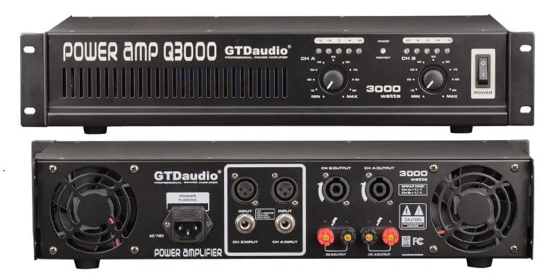
Power Amplifier Basics:
It is the most used amplifier in the electronics circuit and is also known as large signal amplifiers .
The main features of the large-signal amplifiers are the circuit power efficiency, impedance matching to the output device and the maximum amount of power that the circuit is capable of handling.
Power Amplification
As per the law of conservation of energy, the power amplifier cannot amplify power . The power amplifier is just a DC to AC power converter whose action is controlled by the input signal.
During operation, it takes DC power from the supply connected to the output circuit and converts it into useful AC signal. The type of AC power developed at the output of the power amplifier is controlled by the input signal. Thus, whatsoever power is developed is fed to the load i.e. loudspeaker.
Power Amplifier Properties
The performance of the power amplifier is understood on the basis of quantities like collector efficiency, power dissipation capability, and distortion. We will discuss all such properties one by one. Read on to learn more
The change in the shape of the output waveform of the input waveform of an amplifier is known as Distortion.
When the output wave shape is not an exact replica of the input wave shape, the amplifier is said to have some distortion.
As compare to the voltage amplifiers, power amplifiers handle larger signals. Hence in these amplifiers, the problem of distortion occurs immediately. So in this type of amplifier, we have to take care of this factor a lot.
Collector Efficiency
The collector efficiency or efficiency of the collector of an amplifier is defined as the ratio of AC output power to the DC input power or zero signal power of a power amplifier.
Collector efficiency tells us the percentage of DC power converted into AC power by the amplifier.
For example, if the DC power supplied by the source is 10W and AC output power is 4W, then the collector efficiency is 40% i.e. the greater the collector efficiency, the better is the amplifier.
Collector efficiency Equation Derivation
Mathematical expression equation of collector efficiency is given as:
η = AC power output / DC power input
η = P ac / P dc
As we know,
η = V ce I c / V cc I c
Therefore, collector efficiency is also given as;
η = [V ce (peak to peak) * I c (peak to peak)] / 8 V cc I c
Power Dissipation capability
During operation, the ability of power transistor to dissipate the heat developed in it is known as its power dissipation capability.
As we know, power transistors used in a power amplifier carry large current during operation. This heats up the collector junction.
The rise in temperature influences the operating conditions of the transistor. Therefore, the transistor used must be capable of dissipating this heat to the surroundings.
Classification of Power Amplifier
When power amplifier handles large signals, sometimes many of them are driven so hard by the input signals that the collector current reaches either in the cut-off or in the saturation regions during its peak values.
As we know audio waves have small frequency range and radio waves have a large frequency range. Mainly these are divided into two categories according to the range of signals they amplify.
Audio Power Amplifier
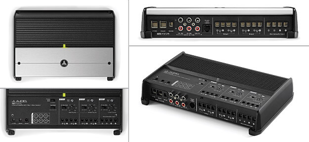
These are known as the small-signal amplifier . These can generally raise the power levels of signals having audio frequency range i.e. 20 Hz to 20 kHz. In an audio playback system, it is the electronics’ final stage.
Radio Power Amplifier
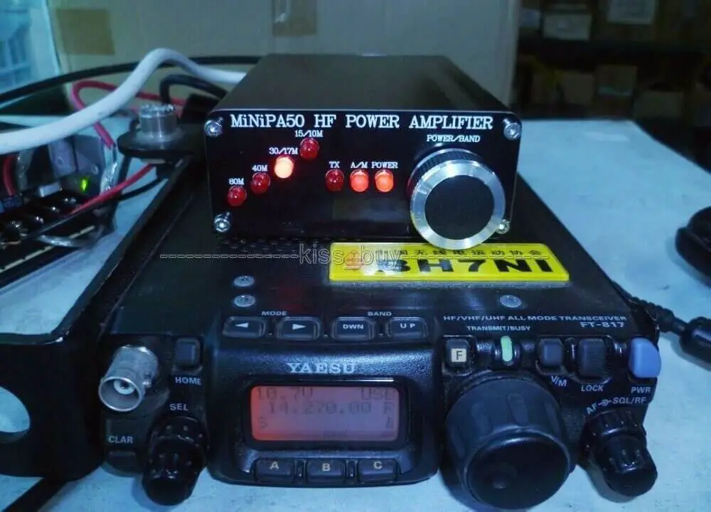
[Image source]
These are known as the large signal amplifiers . These raise the power levels of signals that have the radio frequency range.
It basically converts a low-power radio-frequency signal into a higher power signal and amplifies a specific frequency or narrow band of frequencies & rejecting all other frequencies.
On the basis of mode of operation i.e. the portion of the input cycle during which the collector current flows through the circuit, it is classified into four classes:
- Class A
- Class B
The detailed post about these classes are published now:
[irp posts=”1301″ name=”Power Amplifier Circuit, Classes and its Characteristics”]
Hope you all like this article. For any suggestions please comment below. We always appreciate your suggestions.
Help Your Friends
Thanks Chris for stopping on my blog and dropping your valuable comment. Always feel free to ask any question related to electronics.
- Pingback: Push-Pull Amplifier: Circuit & Operation | Analyse A Meter
- Pingback: Class A power Amp: Theory & Efficiency | Analyse A meter
Leave a Reply Cancel reply
Your email address will not be published. Required fields are marked *
Save my name, email, and website in this browser for the next time I comment.
This site uses Akismet to reduce spam. Learn how your comment data is processed .

- Amplifiers Tutorial
- Amplifiers - Home
- Materials - Introduction
- Transistors
- Transistors - Overview
- Transistor Configurations
- Transistor Regions of Operation
- Transistor Load Line Analysis
- Operating Point
- Transistor as an Amplifier
- Transistor Biasing
- Methods of Transistor Biasing
- Bias Compensation
- Basic Amplifier
- Classification of Amplifiers
- Based on Configurations
- Multi-Stage Transistor Amplifier
- RC Coupling Amplifier
- Transformer Coupled Amplifier
- Direct Coupled Amplifier
Power Amplifiers
- Classification of Power Amplifiers
- Class A Power Amplifiers
- Transformer Coupled Class A Power Amplifier
- Push-Pull Class A Power Amplifier
- Class B Power Amplifier
- Class AB and C Power Amplifiers
- Tuned Amplifiers
- Types of Tuned Amplifiers
- Feedback Amplifiers
- Negative Feedback Amplifiers
- Emitter Follower & Darlington Amplifier
- Noise in Amplifiers
- Amplifiers Useful Resources
- Amplifiers - Quick Guide
- Amplifiers - Useful Resources
- Amplifiers - Discussion
- Selected Reading
- UPSC IAS Exams Notes
- Developer's Best Practices
- Questions and Answers
- Effective Resume Writing
- HR Interview Questions
- Computer Glossary
In practice, any amplifier consists of few stages of amplification. If we consider audio amplification, it has several stages of amplification, depending upon our requirement.

Power Amplifier
After the audio signal is converted into electrical signal, it has several voltage amplifications done, after which the power amplification of the amplified signal is done just before the loud speaker stage. This is clearly shown in the below figure.

While the voltage amplifier raises the voltage level of the signal, the power amplifier raises the power level of the signal. Besides raising the power level, it can also be said that a power amplifier is a device which converts DC power to AC power and whose action is controlled by the input signal.
The DC power is distributed according to the relation,
DC power input = AC power output + losses
Power Transistor
For such Power amplification, a normal transistor would not do. A transistor that is manufactured to suit the purpose of power amplification is called as a Power transistor .
A Power transistor differs from the other transistors, in the following factors.
It is larger in size, in order to handle large powers.
The collector region of the transistor is made large and a heat sink is placed at the collector-base junction in order to minimize heat generated.
The emitter and base regions of a power transistor are heavily doped.
Due to the low input resistance, it requires low input power.
Hence there is a lot of difference in voltage amplification and power amplification. So, let us now try to get into the details to understand the differences between a voltage amplifier and a power amplifier.
Difference between Voltage and Power Amplifiers
Let us try to differentiate between voltage and power amplifier.
Voltage Amplifier
The function of a voltage amplifier is to raise the voltage level of the signal. A voltage amplifier is designed to achieve maximum voltage amplification.
The voltage gain of an amplifier is given by
$$A_v = \beta \left (\frac{R_c}{R_{in}} \right )$$
The characteristics of a voltage amplifier are as follows −
The base of the transistor should be thin and hence the value of β should be greater than 100.
The resistance of the input resistor R in should be low when compared to collector load R C .
The collector load R C should be relatively high. To permit high collector load, the voltage amplifiers are always operated at low collector current.
The voltage amplifiers are used for small signal voltages.
The function of a power amplifier is to raise the power level of input signal. It is required to deliver a large amount of power and has to handle large current.
The characteristics of a power amplifier are as follows −
The base of transistor is made thicken to handle large currents. The value of β being (β > 100) high.
The size of the transistor is made larger, in order to dissipate more heat, which is produced during transistor operation.
Transformer coupling is used for impedance matching.
Collector resistance is made low.
The comparison between voltage and power amplifiers is given below in a tabular form.
| S.No | Particular | Voltage Amplifier | Power Amplifier |
|---|---|---|---|
| 1 | β | High (>100) | Low (5 to 20) |
| 2 | R | High (4-10 KΩ) | Low (5 to 20 Ω) |
| 3 | Coupling | Usually R-C coupling | Invariably transformer coupling |
| 4 | Input voltage | Low (a few m V) | High (2-4 V) |
| 5 | Collector current | Low (≈ 1 mA) | High (> 100 mA) |
| 6 | Power output | Low | High |
| 7 | Output impendence | High (≈ 12 K Ω) | Low (200 Ω) |

Power Amplifiers and various types
Introduction To Power Amplifiers
An amplifier system consists of signal pick-up transducer, followed by a small signal amplifier(s), a large signal amplifier and an output transducer. A transducer is used to convert one form of energy into another type. For example a microphone is used to convert acoustical energy into electrical energy. Conversely, a loudspeaker is used to convert electrical energy into acoustical energy. A motor is a transducer that is used to convert electrical energy into mechanical energy.
The input transducer produces small electrical (typically voltage) signal, that needs sufficient amplification to operate some output device such as a loudspeaker, a servomotor, a solenoid or relay. The factors of prime interest in small signal voltage amplifiers are usually linearity and gain. Since the signal voltage and current from the input transducer is usually very small, the amount of power handling capacity and power efficiency are of slight concern. The functions of voltage amplifiers are to present a high resistance to the input transducer to minimize loading effects and to provide a large enough voltage signal to the large-signal amplifier stages to operate such output devices (loudspeaker, servomotor etc.). A large-signal amplifier must operate efficiently and be capable of handling large amounts of power-typically, a few watts to hundred of watts. Large signal amplifier that drives the output transducer demands even more consideration than the small-signal voltage amplifiers that we have focused so far. The factors of greatest concern to the large signal power amplifiers are the power efficiency of the circuit, the maximum amount of power that the circuit is capable of handling, and impedance matching to the output device.
Power amplifier is meant to raise the power level of the input signal. In order to get large power at the output, it is necessary that the input-signal voltage is large. That is why, in an electronic system, a voltage amplifier always precedes the power amplifier, also, that is why power amplifiers are called large-signal amplifiers.
In fact, power amplifier does not amplify power. What a power amplifier actually does is that it draws power from dc supply connected to the output circuit and converts it into useful ac signal power. The type of ac power available at the output terminals of the power amplifier is controlled by the input signal. Thus a power amplifier may be defined as a device that converts dc power and whose action is controlled by the input signal.
The transistors employed in power amplifiers are called power transistors. They differ from other transistors in the following respects.
(i) The base is made thicker to handle large currents i.e.in power amplifiers; transistors with comparatively smaller gain are used.
(ii) The area of collector region of a power transistor is made considerably larger in order to dissipate the heat developed in the transistor during operation. Moreover, heat sinks are used for improving the heat dissipation.
(iii) The emitter and base layers are heavily doped. The contact area between the base layers and base leads is in ring like form so that the area is increased. By doing so ohmic resistance between emitter and base is reduced and due to low resistance, small power is required at input.
Classification Of Power Amplifiers
The power amplifiers are primarily divided into two categories
- Audio-power amplifiers – also called the small signal power amplifiers, raise the power levels of signals that have audio-frequency range (20 Hz- 20 kHz).
- Radio-power amplifiers – also called large signal power amplifiers raise the power level of signals that have radio frequency range. They amplify a specific frequency or narrow band of frequencies while rejecting all other frequencies.
Classification According To Mode of Operation
Transistor power amplifiers handle large signals. Many of them are driven so hard by the input large signal that collector current is either cut- off or is in saturation region during a large portion of the input cycle. So such amplifiers are generally classified according to their mode of operation. This classification is based on the amount of transistor bias and amplitude of the input signal. It takes into account the portion of the cycle for which the transistor conducts. They are classified as below:
- Class A Power Amplifiers – In this case, transistor is so biased that the output current flows for the entire cycle of the input signal. Thus the operating point is so selected that the transistor operates only over the linear region of its load line. So such an amplifier can amplify input signal of small amplitude. As the transistor operates over the linear portion of load line, the output waveform is exactly similar to input waveform. So class A amplifiers are characterised by a high fidelity of the output. Such amplifiers are used where freedom from distortion is prime aim. Operation is restricted only over a small central region of the load line so such amplifiers can be used for amplifying signals of small amplitude. Also ac power output per transistor is small. The maximum possible overall efficiency with resistive load is 25%. The maximum possible collector efficiency with resistive load is 50%. In case an output transformer is used, both of these efficiencies are 50%.
- Class B Power Amplifiers – In this case, the transistor bias and signal amplitude are such that output current flows only during positive half cycle of the input signal. At zero signals, the collector current is zero and no biasing system is required in class B amplifiers. The operating point is selected at collector cut-off voltage; Because of total absence of negative half cycle from the output the signal distortion is high. Zero signal input represents the best condition for class B amplifiers because of zero collectors current. The transistor dissipates more power with increase in signal strength. In comparison to class A amplifiers average current is less, power dissipation is less. So overall efficiency is increased. The theoretical efficiency in class B operation is about 78.5% while it is only 50% in class A operation.
- Class AB Power Amplifiers – An amplifier may be biased at a dc level above the zero base current level of class B power amplifiers and above one-half the supply voltage level of class A; this bias condition is class AB. Class AB operation still needs a push-pull connection to achieve a full output cycle, but the dc bias level is usually closer to zero base current level for better power efficiency. For class AB operation the output signal swing occurs between 180 degree and 360 degree and is neither class A nor class B operation.
- Class C Power Amplifiers – A class C power amplifier is biased for operation for less than 180 of the input signal cycle and will operate only with a tuned or resonant circuit which provides a full cycle of operation for the tuned or resonant frequency. Such power amplifiers are, therefore, employed in special areas of tuned circuits, such as radio or communications.
- Class D Power Amplifiers – Class D power amplifiers are designed to operate with digital or pulse type signals. Using digital techniques makes it possible to have a signal that varies over the entire cycle (using sample-and-hold-circuitry) to recreate the output from many pieces of input signal. The main advantage of class D power amplifiers is that it is on (using power) only for short intervals and the overall efficiency can practically be very high (above 90 degree).
Normal 0 false false false EN-IN X-NONE X-NONE MicrosoftInternetExplorer4
Related Posts
Q switching: types of q switches and applications, do you know how rfid wallets work and how to make one yourself, rheostat – working, construction, types & uses.
August 21, 2009
Dear John, 1. In fact, power amplifier does not amplify power.
While this is basically true, incomming signal is amplified, and to do so, it requires Operating power which is dervied from DC. — 2 Class D Power Amplifiers: … overall efficiency can practically be very high (above 90 degree).
This I think should read 90%. — Incidentally,
I would love to see a circuit for DC volume control or Gain control of about 80 dB. Linear control is preferred rather then log, since may application is truly not for Volume control. List of ICs performing the required function is welcome. With regards, Laxman Khalkar
Type above and press Enter to search. Press Esc to cancel.

Power Amplifier | Types of Power Amplifier

Power Amplifiers
To deliver a large power to a load, a specially designed amplifier called a “Power Amplifier” is used as a final stage as shown in the figure below.
It is called the “Large Signal Amplifier” because it is capable of supplying an adequately large amount of power to the load like a loudspeaker.

The primary aim of a power amplifier is to supply a large power therefore the voltage gain is not important.
Power amplifiers are used as the last stage in the P.A system, radio receivers , TV receivers, etc.
Some of the important features of power amplifiers are as follows:
- Impedance matching with the load is necessary for the maximum transfer of power.
- They use power transistors.
- Power amplifiers are bulky due to the use of heat sinks.
- Harmonic distortion is present in the output.
- They are capable of handling a large power.
Depending on the position of the Q-point or operating point on the load line, the Power amplifiers are classified into the following four categories:
- Class-A amplifiers
- Class-B amplifiers
- Class-C amplifiers
- Class-AB amplifiers
Read More: Classification of Different Amplifier
This classification has been done on the basis of the Q-point on the load line.
The types of amplifiers and the position of the Q-point are listed below table:
| Sr. NO | Type of amplifier | Position of Q-point |
|---|---|---|
| 1. | Class-A | At the center of the load line |
| 2. | Class-B | In the cutoff region |
| 3. | Class-AB | Just above the cutoff |
| 4. | Class-C | Below the cutoff |
Table of Contents
Class-A Power Amplifier
- An amplifier is referred to as a class A amplifier if the transistor used for amplification conducts for the full cycle duration of the input ac signal.

- The Q-point is adjusted exactly at the center of the load line as shown in the figure below.
- Due to this, the output signal is obtained for the full cycle of the ac input. i.e. 360 o .
- The power transistor is biased such that the operating point (Q-point) is approximately at the center of the load line.
- Now, when we apply the ac signal to the base of the power transistor, the base current changes sinusoidally above and below the quiescent base current I BQ .
- In response to the changes in I B , the collector current changes sinusoidally above and below its quiescent current value I CQ . The collector current and base currents are in phase with each other.
- Due to changes in IC, the voltage VCE will also fluctuate sinusoidally.
Note: V CE and I C are 180 o out of phase.
Operation of Class-A Power Amplifier

- The transistor remains in the “ active region ” for all the values of the input signal and never enters into the saturation or cutoff regions. So class-A power amplifiers are linear amplifiers .
- The transistor conducts the complete cycle of ac input i.e. for 360°. Thus the angle of collector current flow is 360° or a full cycle.
- As shown above figure, the input signal is amplified faithfully, without introducing any distortions. Thus harmonic contents in the output will be low.
- As the transistor continuously operates in its active region, the voltage V CE across it and current I c . through it, both are simultaneously high.
- Therefore a large power will be dissipated in the transistor in the form of heat.
- Therefore the efficiency of class A power amplifiers is low. In fact, it is the lowest of all the power amplifiers.
- Typically the efficiency (n) of a class A power amplifier lies between 25% to 50% .
Advantages of class A power amplifier
- Simple construction.
- Distortionless output voltage.
Disadvantages of class A power amplifier
- Very low efficiency (25% or 50%)
- Large power dissipation in the power transistors.
Class-B Power Amplifier
- An amplifier is referred to as a class B amplifier if the output signal is obtained only for one half-cycle period of the input ac signal.

- The transistor conducts only in a one-half cycle of the input and the collector current, therefore, flows for only 180°, as shown in the below figure.
- For this, the Q point is adjusted to be a cut-off. i.e. on the X-axis as shown in the below figure. Thus in the absence of an ac input signal, the transistor remains in the off state.
- The coordinates of the Q-point are (Vcc, 0).
Operation of Class-B power amplifier

- As we apply a sinusoidal input signal to the base of the transistor, the B-E junction of the transistor is forward-biased only during the positive half cycle of the input and the base current starts flowing.
- The transistor remains in the active region, only for the positive half cycle of the input signal In the negative half cycle, the transistor remains in the off state. Thus collector current flows for only 180° (half cycle) of the input signal.
- As seen from the above figure, only one-half cycle is obtained at the output. Therefore the output voltage waveform is distorted because it is no more a sinewave.
- The distortion can be eliminated by using two transistors in alternate half cycles of the input signal to produce the complete cycle of the signal at the output. Each transistor conducts only 180°. This is called the push-pull class B power amplifier.
- As the transistor remains off for the complete negative half cycle, the power dissipation in the transistor is reduced as compared to that in the class A power amplifier.
- Therefore the efficiency of class B amplifiers is higher than that of class A power amplifiers.
- The maximum efficiency of the class-B configuration can be 78.5% which is much higher than that of the class-A power amplifier.
Crossover Distortion
- The waveform distortion near the zero-crossing points is observed in class B power amplifiers.
- This happens because the transistors are biased at cut-off.
- The crossover distortion can be eliminated by using the class-AB type power amplifier.
Advantages of class B power amplifier
- Higher efficiency (78.5%)
- Zero power dissipation under quiescent conditions.
- Impedance matching with load is possible.
- The second harmonic component gets automatically canceled.
Disadvantages of class B power amplifier
- Crossover distortion is present in the output waveform.
- Efficiency is not so high.
Class-AB Power Amplifier
An amplifier is referred to as a class AB amplifier if the output signal is obtained for more than 180 o but less than 360 o of the ac input signal.

That means the power transistor connected in a class AB power amplifier will conduct for more than 180 o but less than 360 o of the ac input.
For this, the Q-point is positioned slightly above the cutoff. Thus in absence of an ac input signal, the transistor is “Just conducting”.
Operation of Class-AB Power Amplifier

- In order to obtain the output signal for more than 180° and less than 360° of the ac input signal. the Q point is positioned slightly above the X-axis but below the mid-point of the load line.
- The transistor conducts for the complete positive half cycle and a part of the negative half cycle of the input signal.
- The output signal is distorted. However, this distortion can be eliminated by using two transistors which can conduct in the alternate half cycles of the input. The class AB operation is helpful in eliminating cross-over distortion.
- The Q point is neither in the middle of the load line like the class A operation nor on the X-axis like class B. It is in between the two. Therefore the name class AB operation. The transistor conducts for more than 180° (class B) but less than 360° (class A), therefore the power dissipation in the transistor is less than that in class A operation and more than that in the class B operation.
- Hence the efficiency of the class AB power amplifier is higher than class A but less than the class B power amplifier.
Advantage of class AB power amplifier
- The biggest advantage of class AB amplifiers is the elimination of crossover distortion.
- Hence this configuration is preferred in all audio systems, radio, TV receivers, etc.
Class C Power Amplifier
- An amplifier is referred to as a class C power amplifier if its output is obtained for less than a half-cycle period of the input ac signal.

- Thus the power transistor in a class C configuration will conduct for a duration that is less than the period of a half cycle of the ac input signal.
- For this, the operating point is adjusted to be below the X-axis as shown in Figure below. Thus the transistor is biased below the cut-off.
Operation of Class C Power Amplifier

- Due to the biasing below the cut-off, the transistor can remain in the active region for less than a half-cycle period. Thus collector current flows for less than 180°. In other words, the conduction angle is less than 180°.
- Due to the reduced conduction angle, the output signal is heavily distorted. The percent distortion is higher than that for a class B power amplifier. Therefore class C power amplifiers are not used as A.F. power amplifiers.
- The efficiency of class C amplifiers is very high. In fact, it is the highest of all the power amplifiers.
- Typically the efficiency is above 95%.
Advantage of class C power amplifier
- Very high efficiency (higher than 95%).
- Low power loss in the power transistors.
The disadvantage of class C power amplifier
- The output waveform can be distorted.
Applications of class C power amplifier
- Class C amplifiers generally use a tuned circuit as a load. Such amplifiers are called class – C tuned amplifiers.
- These amplifiers are used as the collector modulator to produce the amplitude-modulated signal.
comparison of power amplifiers
| Sr. No | Parameter | Class A | Class B | Class C | Class AB |
|---|---|---|---|---|---|
| 1. | Conduction angle of collector current | 360 or full-cycle | 180 or half cycle | Less than 180 | Between 180 and 360 |
| 2. | Position of Q-point on the load line | At the center | On the X-axis | Below the X-axis | Above the X-axis but below the midpoint |
| 3. | Distortion in output voltage | No distortion | More than class-A (Crossover) | More than A, B, and AB | Low |
| 4. | Efficiency | Lowest 25% to 50% | Higher (78.5%) | Very High(95%) | Between 50 and 78.5% |
| 5. | Power dissipation in transistors | Very high | Low | Very low | Moderate |
Frequently Asked Questions on Power Amplifiers
Answer: A power amplifier (PA) converts a low-power signal to a higher-power one . Two common examples are audio amplifiers, used to drive loudspeakers and headphones, and RF power amplifiers, such as those used in the final stage of a transmitter.
Answer: High-power amplifiers are used in the transmission of cellular or FM broadcasting signals to users, in the control of most industrial actuator systems such as servos and DC motors, and in almost all consumer electronic devices such as microwave ovens, televisions, mobile phones, headphone drivers, home theater systems
Answer: Crossover distortion is a type of distortion that is caused by switching between devices driving a load . It is most commonly seen in complementary, or “push-pull”, Class-B amplifier stages, although it is occasionally seen in other types of circuits as well.
Answer: The cross-over distortion in the class B power amplifier is eliminated by the Class AB power amplifier which uses diodes at the bases of transistors to reduce forward bias voltage at bases i.e. by biasing the transistors slightly above the cut-off.
Hello friends, my name is Trupal Bhavsar, I am the Writer and Founder of this blog. I am Electronics Engineer(2014 pass out), Currently working as Junior Telecom Officer(B.S.N.L.) also I do Project Development, PCB designing and Teaching of Electronics Subjects.
Leave a Comment Cancel reply
Save my name, email, and website in this browser for the next time I comment.
This site uses Akismet to reduce spam. Learn how your comment data is processed .


Difference Between Voltage Amplifier and Power Amplifier
Voltage and power are the two major classifications of amplifiers and the classification is done on the basis of the comparison made according to the characteristics of applied input and generated output signal. The crucial difference between a voltage amplifier and a power amplifier is that a voltage amplifier increases the voltage level of the applied input signal. As against, a power amplifier is the one that boosts the power level of the input signal.
What is an Amplifier?
An amplifier is an electronic device that boosts the level of the signal present at its input and provides the raised but identical signal at the output. Thus, it is a device that serves the purpose of amplification. The factor that determines the level of the amplification given by the amplifying unit is known as the gain of the amplifier.
Generally, various applications require very large output signals which a single amplifying unit fails to provide. So, sometimes there is a cascade connection of amplifiers in which the output of one, acts as input to the next and so on. In this way, we get multistage amplification of the signal. Here in this article, we will discuss the differentiating factors between voltage and power amplifiers.
Content: Voltage Amplifier Vs Power Amplifier
Comparison chart.
- Key Differences
| Basis for Comparison | Voltage Amplifier | Power Amplifier |
|---|---|---|
| Basic | It raises the voltage level. | It provides increase in the power level. |
| Known as | Small signal amplifier | Large signal amplifier |
| Magnitude of input signal | Small | Comparatively large |
| Type of coupling used | RC coupling | Transformer coupling |
| Base region | The base region of transistor is thin. | Here the base of transistor is comparatively thicker. |
| Value of I | Low, approximately around 1 mA. | Quite high, nearly 100 mA. |
| Achieved ac power | Low | Very high |
| Value of β | Low (5 to 20) | High (100) |
| Physical size of transistor | Small | Generally large |
| Heat dissipation | Less | More |
| Load impedance | High (4 kΩ to 10 kΩ) | Low (5 to 20 Ω) |
Definition of Voltage Amplifier
Here the name itself is indicating that it is an amplifier whose operation is associated with voltage. So, an amplification unit is designed to increase the level of voltage of the applied input signal and it is known as a voltage amplifier.

Suppose if the applied input signal voltage is 1 V and the output voltage after amplification is 25 V then the voltage gain will be 25, where the gain is a unitless quantity. These amplifiers are the device that draws a very little amount of power from the load. These are referred as small-signal amplifiers as here the magnitude of the signal which is actually given as input is very small which is raised by the amplifier circuit.
Definition of power amplifier
A power amplifier is a device that is designed to boost the power level of the signal present at the input. Basically, to have large power at the output, a signal having a large magnitude of signal voltage must be present at the input. This is the reason generally a voltage amplifier is present before a power amplifier.
Now some questions must be answered like what is the need for such a high voltage signal at the input and do you actually think that power can be amplified?
The answer to both the questions is that power can never be directly amplified as no device can do so. Basically, a power amplifier changes the dc power collected from an output circuit into an ac signal power. The high signal voltage at the input generates a high signal current, the product of which provides high output power.
As the ac power is controlled by the applied input signal, this is the reason, the power amplifier is regarded as a dc to ac power converter whose value is controlled by the input signal.
So, the power gain of the amplifier will be:
Key Differences Between Voltage Amplifier and Power Amplifier
- The voltage amplifier is designed to amplify voltage while the power amplifier amplifies the power level of the signal.
- Voltage amplifiers have an input signal of small magnitude thus is known as a small-signal amplifier. Whereas power amplifiers require input signal of comparatively larger magnitude thus is known as a large-signal amplifier.
- The base of the transistor in the voltage amplifier circuit is thin as it does not design to handle the large current. But as a power amplifier must handle large current, therefore, has a comparatively thicker base region.
- Generally, low or medium power transistors that have a smaller physical size is used to design a voltage amplifier. However, high power transistors having a large physical size is used for power amplifiers.
- In the case of the voltage amplifier, the value of the collector current is quite low, ranges nearly 1 mA. While for power amplifiers the collector current is a high value of around 100 mA.
- The amount of ac output power delivered by the power amplifier is quite high in comparison to the ac output power provided by the voltage amplifier.
- The current gain offered by a voltage amplifier is lesser than that offered by the power amplifier.
- A voltage amplifier is RC coupled whereas a power amplifier is transformer coupled.
- The load impedance of a power amplifier with a value of nearly 5 to 20 Ω is comparatively less than that of a voltage amplifier with a range between 4 to 10 KΩ.
- The heat dissipation is less in the case of a voltage amplifier than a power amplifier. Therefore, a cooling system is necessary for a power amplifier rather than a voltage amplifier.
Hence the above discussion concludes that both voltage and power amplifiers have their own operating zones based on the advantages offered by the two. A voltage amplifier gives a raised value of the input value as output. While for a power amplifier the product of current and voltage achieved at the output is higher than that present at the input.
Related terms:
- Difference Between Inverting and Non-Inverting Amplifier
- Working Voltage in Power System
- Voltage Stability in Power System
- Methods of Voltage Control in Power System
- Difference Between EMF and Voltage
3 thoughts on “Difference Between Voltage Amplifier and Power Amplifier”
Very nice 👌👌👍
Thanks for this knowledge. It’s helpful.
That’s nicely described..! Thank you..!
Leave a Comment Cancel Reply
Your email address will not be published. Required fields are marked *
Save my name, email, and website in this browser for the next time I comment.
Power Amplifiers
Aug 24, 2014
2.21k likes | 5.43k Views
Power Amplifiers. Power Amplifiers are used in the transmitter There are different classes for the power amplifier Class A, Class B, Class AB, Class C, Class D and Class E
Share Presentation
- great importance
- power amplifiers class c
- average output power
- power amplifiers
- normalized peak collector current
- collector current

Presentation Transcript
Power Amplifiers Power Amplifiers are used in the transmitter There are different classes for the power amplifier Class A, Class B, Class AB, Class C, Class D and Class E Those amplifier differs in their angle of conduction, efficiency, linearity and the in the amount of distortion they introduce to the system
Power Amplifiers • Class A • The amplifier conducts through the full 360 of the input. The Q-point is set near the middle of the load line. • Class B • The amplifier conducts through 180 of the input. The Q-point is set at the cutoff point.
Power Amplifiers • Class AB • This is a compromise between the class A and B amplifiers. The amplifier conducts somewhere between 180 and 360 . The Q-point is located between the mid-point and cutoff. • Class C • The amplifier conducts less than 180 of the input. The Q-point is located below the cutoff level.
Power Amplifiers • Class D • This is an amplifier that is biased especially for digital signals.
Class C power amplifiers Class C amplifier is obtained if the output current conduction angle is less than 180 Class C have a greater efficiency than both class A and class B Class C also have larger distortion compared with the A and B Class C amplifier is used when there is no variation in signal amplitude and the output circuit contains a tuned circuit to filter out the harmonics Class C amplifier is used for applications similar to FM Modulation
Class C power amplifiers The output of the class C conducts for less than 180 of the AC cycle The Q-point is below cutoff as shown below
Power Amplifiers Class C
Class C power amplifier The circuit shown to the left will be considered in analysis of the class C amplifier
Class C power amplifier • The amplifier efficiency can be computed from the following equation • The output power is the AC power flowing in the load resistance • The input power is the supply power which can be determined from the multiplication of the supply voltage and the average collector current • The main step in the analysis is to compute the average collector current which is explained in the next slide
Class C power amplifier • According to the figure shown to the left, the collector current is given by • Where ID is given by
Class C power amplifier • The direct collector current is determined by its average value which is given by • It is desired to find the current as a function of the angles θ1 and θ2 rather than t1 and t2 • This can be achieved by using the following mapping and
Class C power amplifier • The average collector current can be rewritten as • By evaluating this equation we may have the following expression • To simplify the notation, the conduction angle will be defined as ICav
Class C power amplifier • By substituting the conduction angle expression into the average collector current equation we get • Now the supplied input power can be written as • If the output RLC circuit is a narrow band filter tuned to the fundamental frequency of the current pulses, then the output power will be
Class C power amplifier • Where I1 is the amplitude of the fundamental current components which is determined by the trigonometric Fourier series as shown below • By solving the previous equation we may have • The output power now can be written as
Class C power amplifier • The efficiency of the amplifier can be written as • A plot of the efficiency as a a function of the conduction angle is shown below
Class C power amplifier design There are four important design parameters are of great importance for PA design in general These parameters are The output power Transistor power dissipation Maximum collector to emitter voltage VCEmax The maximum transistor output current Ip
Class C power amplifier design The maximum collector current is given by Since The collector current can be rewritten as The maximum current in terms of the output current can be written as Note that the value of the collector voltage VCC can be written as
Class C power amplifier design Now the maximum collector current can be rewritten as A normalized peak collector current is defined as
Class C power amplifier design A plot of the normalized peak current versus the conduction angle is shown below
Class C power amplifier design The power dissipated in the transistor is given by Note the value of Ip can be expressed as From we can conclude that If the value of Ip is substituted in the PT equation then
Class C power amplifier design The power dissipated in the transistor is given by Or PT can be rewritten as
Class C power amplifier design A normalized plot of PT/PO versus theta is shown below
Class C power amplifier design example Example: Design a class C amplifier that will deliver 5-W average power to a 50 Ω load at a frequency of 1 MHz using a transistor with a safe power dissipation rating of 0.5 W Solution: The average output power is given by Or
Class C power amplifier design example Solution: Since the allowable power dissipation is The maximum conduction angle can be found from the graph shown in slide 19 or by solving the PT/PO equation The value of the normalized current corresponds to this angle is refer to the figure in slide 16 The peak collector current is given by
Class C power amplifier design An alternate design procedure for class C amplifiers is Select the power supply Select the transistor Determine the maximum output power without exceeding the transistor ratings The transistor then can be driven to its maximum allowed value of output current Determine the value of the load resistance that twill result in the maximum current according to
Class C power amplifier design Now the transistor power equation can be modified as The normalized transistor power dissipation is given by Where
Class C power amplifier design
Class C power amplifier design example 2 Example 2: Determine the maximum output power and the conduction angle of a class C amplifier using a transistor with maximum power dissipation rating of 4 W and a maximum output current of 1.5 A. The supply voltage is 48 V Solution: The normalized maximum transistor dissipation is given by
Class C power amplifier design example 2 Solution: The conduction angle for maximum normalized transistor power P΄Tis found to be as If we refer back (PT/PO vs θ ) plot we find that the value of PT/PO which corresponds to this angle is The output power now can be found as
Class C power amplifier design example 2 Solution: Finally the value of the load resistance that results in this output power is given by
- More by User

POWER AMPLIFIERS… Cont
POWER AMPLIFIERS… Cont. Why is class A so inefficient ?. Single transistor can only conduct in one direction. D.C. bias current is needed to cope with negative going signals. 75 % (or more) of the supplied power is dissipated by d.c. Solution : eliminate the bias current.
981 views • 26 slides
Output Stages and Power Amplifiers
435 views • 27 slides

Tetrode Power Amplifiers
TIARA & Uppsala University Workshop on RF Power Generation for Accelerators Eric Montesinos , CERN, BE-RF-PM. Tetrode Power Amplifiers. Introduction. Workshop on novel concepts for RF power generation for accelerators
669 views • 33 slides

Manufacturer Of Linear Power Supplies & Power Amplifiers
http://www.amp-line.com/ is a manufacturer of general and special purpose linear power supplies and power amplifiers for the industrial and scientific research market. We provide flexible, advanced, and reliable AC power solutions in the audio and ultrasound frequency ranges (from 5 Hz to 800K Hz). Our products are utilized in applications such as testing of Helmholtz coils, piezo elements, circuit breakers, protective relays, lamps, watt-meters, transformers, inductors, capacitors, ferrite cores, arrestors, MOVs, etc. Our products are ideal for highly inductive loads and capacitive loads which require PD free powering.
347 views • 18 slides
Chapter 12 Power Amplifiers
Chapter 12 Power Amplifiers. 12.1 General Considerations 12.2 Classification of Power Amplifiers 12.3 High-Efficiency Power Amplifiers 12.4 Cascode Output Stages 12.5 Large-Signal Impedance Matching 12.6 Basic Linearization Techniques 12.7 Polar Modulation 12.8 Outphasing
2.88k views • 107 slides
Power Amplifiers and Loudspeakers
Power Amplifiers and Loudspeakers. Power amp ratings Loudspeaker types and uses. Power Amplifiers. An amplifier is an electronic device which transforms small voltages and currents into large ones. Ratings Wattage Generally speaking more is better
439 views • 19 slides
Power Amplifiers. Unit – 4.1. Classification of Power Amplifiers. Power amplifiers are classified based on the Q point If the operating point is chosen at the middle of the load line, it is called Class A amplifier
1.17k views • 36 slides

Power Amplifiers. 25 FEB 2013. Basics …. In mathematical terms, if the input signal is denoted as S , the output of a perfect amplifier is X*S , where X is a constant (a fixed number). The "*" symbol means ”multiplied by". No amplifier does exactly the ideal. Contd.
1.13k views • 79 slides
Untuned and Tuned Power Amplifiers
Untuned and Tuned Power Amplifiers. Amplifier classification Class B amplifier operation Transformer-coupled push-pull stages Tuned power amplifiers Power dissipation considerations. Introduction.
1.28k views • 27 slides

POWER AMPLIFIERS
POWER AMPLIFIERS. PRO and CON By Dave Russell, W2DMR Forest Cummings, W5LQU. Basic power amplifier. RF Drive. PA. AC?. ALC. Cooling. AC Power. PS. POWER AMPLIFIER TYPES. Vacuum Tube High impedance – high voltage – danger! Tuned network – PI – 3:1 VSWR – No Coupler
864 views • 23 slides

High power ultrafast fiber amplifiers
High power ultrafast fiber amplifiers. Yoann Zaouter , E. Cormier CELIA, UMR 5107 CNRS - Université de Bordeaux 1 , France Stephane Gueguen , C. Hönninger, E. Mottay Amplitude Systèmes Pessac , France. [email protected]. Outline of the talk.
632 views • 38 slides

solution inc power amplifiers
solution inc the sole distributor in india
139 views • 8 slides

Power Amplifiers. Power Amplifier. Definitions. In small-signal amplifiers the main factors are: • Amplification • Linearity • Gain Since large-signal, or power, amplifiers handle relatively large voltage signals and current levels, the main factors are: • Efficiency
1.66k views • 57 slides

Classification of power amplifiers
POWER AMPLIFIERS. Classification of power amplifiers. POWER AMPLIFIERS. Required To deliver a large current to a small load resistance e.g. audio speaker; or to deliver a large voltage to a large load resistance e.g. switching power supply;
1.14k views • 28 slides
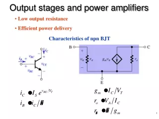
Output stages and power amplifiers
Output stages and power amplifiers. Low output resistance Efficient power delivery. Characteristics of npn BJT. Classification of Output Stages. Class B. sinusoidal input signal. Class A. Class AB. Class A Output Stage. emitter follower. Class A Output Stage. transfer characteristic.
151 views • 11 slides

Power Amplifiers. BASICS. Power amplifiers get the necessary energy for amplification of input signals from the AC wall outlet to which they are plugged into.
873 views • 72 slides

Power Amplifiers. Power Amplifiers. 5 Versions. LBB 4421 1x 500W Power amplifier. LBB 4422 2x 250W Power amplifier. LBB 4424 4x 125W Power amplifier. LBB 4426 4x 60W Power amplifier. Discontinued. LBB 4428 8x 60W Power amplifier. Power Amplifiers. 5 Versions.
191 views • 10 slides
- Network Sites:
- Technical Articles
- Market Insights

- Or sign in with
- iHeartRadio

Understanding the Limitations of the Class C Power Amplifier
Join our engineering community sign-in with:, in this article, we explore the drawbacks of class c operation through a performance comparison with class a and class b amplifiers..
As we know from earlier articles in this series, reducing the conduction angle of a power amplifier allows us to increase its efficiency. A Class A stage has a 360 degree conduction angle and a theoretical efficiency of 50%; a Class B amplifier has a 180 degree conduction angle and an efficiency of 78.5%.
This trend toward increased efficiency continues with Class C amplifiers , which use conduction angles lower than 180 degrees. For example, as we see in Figure 1, a Class C amplifier with a conduction angle of 90 degrees has a theoretical efficiency of 94%.

Figure 1. Plot of maximum efficiency vs. conduction angle.
Unfortunately, Class C power amplifiers have several drawbacks that restrict their application in modern solid-state RF circuits. For one thing, they produce considerably less output power than a Class A or B amplifier for the same input power. If we examine the design of a Class C amplifier with the same output power as a Class A or B amplifier, more limitations become apparent.
In this article, we’ll explore these limitations by comparing the performance of Class A, B, and C amplifiers that must deliver a certain RF power to a given load impedance. To keep things simple, we’ll use a 90 degree conduction angle for the Class C amplifier throughout the article. Let’s start by comparing the maximum current that the output transistor of each amplifier carries.
Transistor Current Requirements
In the previous article, we learned how the conduction angle changes the frequency content of the output current. You may recognize Figure 2 from that discussion. It plots the average ( a 0 ) and fundamental ( a 1 ) components against the conduction angle for Class A, B, and C amplifiers. In order for these three designs to deliver the same power, their respective output currents should have identical fundamental components.

Figure 2. The average and fundamental components against the conduction angle.
Note that the a 0 and a 1 coefficients in this figure are normalized to I M , where I M is the peak value of the transistor current. Put a different way, I M is assumed to be unity.
Class A Transistor Current
Let the maximum transistor current in the Class A stage be I MA . From Figure 1, we see that the fundamental component of a Class A stage normalized to I MA is 0.5. We thus have:
$$\frac{a_{1}}{I_{MA}} ~=~ 0.5~ \rightarrow ~a_{1} ~=~ 0.5 I_{MA}$$
Equation 1.
If you can’t immediately figure out why the fundamental component is half the maximum current of the Class A stage, recall that this type of amplifier biases the transistor at the midpoint of its load line. The maximum collector current of an amplifier is the sum of the bias current and the AC current.
To have the maximum symmetrical swing, the DC current through the transistor should be equal to the amplitude of the AC current delivered to the load. Figure 3 shows how the collector current changes in a Class A amplifier when the transistor reaches the boundaries of its load line.

Figure 3. Minimum (a) and maximum (b) collector current In a Class A stage with maximum symmetrical swing.
As you can see, the collector current goes from zero to twice the maximum RF current. This is consistent with Equation 1.
Class B Transistor Current
What about a Class B amplifier? Let the maximum collector current of the Class B stage be I MB . Figure 1 shows that the normalized fundamental component of the Class B stage is also 0.5, giving us:
$$\frac{a_{1}}{I_{MB}} ~=~ 0.5 ~\rightarrow~ a_{1} ~=~ 0.5 I_{MB}$$
Equation 2.
From this, we see that the Class A and Class B amplifiers produce identical fundamental components for a given maximum transistor current.
Class C Transistor Current
The fundamental component of a Class C amplifier depends on its conduction angle. We’re assuming that the conduction angle is θ c = 90 degrees, which corresponds to a normalized fundamental component of 0.31 (Figure 1). We therefore have:
$$\frac{a_{1}}{I_{MC}} ~=~ 0.31 ~\rightarrow~ a_{1} ~=~ 0.31 I_{MC}$$
Equation 3.
where I MC is the maximum collector current of the Class C stage.
Comparing Transistor Currents
To summarize:
- For the Class A amplifier, a 1 = 0.5 I MA .
- For the Class B amplifier, a 1 = 0.5 I MB .
- For the Class C amplifier a 1 = 0.31 I MC
For these three designs to produce the same fundamental component, the following must be true:
$$0.31 I_{MC} ~=~ 0.5 I_{MA} ~=~ 0.5 I_{MB}$$
Equation 4.
Solving for I MC , we obtain:
$$I_{MC} ~=~ 1.6 I_{MA} ~=~ 1.6 I_{MB}$$
Equation 5.
The Class C amplifier’s peak current is 1.6 times that of the Class A or Class B amplifier. Keep in mind that we based our calculations on a Class C amplifier with a 90 degree conduction angle. A Class C amplifier with a conduction angle of less than 90 degrees would have an even higher peak current relative to the Class A or B stage.
The key takeaway here is that the transistor in a Class C amplifier must handle larger currents to produce the same output power. In practical terms, this means that the amplifier needs a larger transistor. The further we reduce the conduction angle, the higher the peak current gets, and the larger the transistor needs to be. This can be problematic—for one thing, a larger transistor leads to a lower matching bandwidth.
The transistor size requirement is a major drawback. There are other efficient power amplifier configurations that don’t need such big transistors, and these have taken over Class C operation in modern solid-state RF design.
When picking a transistor, we also need to consider the amplifier’s maximum voltage. As we’ll see in the next section, Class C operation can run into problems here as well.
The Problem of Reverse Breakdown Voltage
In amplifiers with small conduction angles, swinging the output current to its maximum permissible value requires a large voltage applied to the input of the transistor. To understand why, consider the voltage waveform in Figure 4.

Figure 4. A large input voltage is required when using small conduction angles.
In the above figure:
- θ c is the amplifier’s conduction angle.
- V T is the turn-on voltage of the transistor.
- V max is the input voltage that produces the maximum output current.
The difference between V max and V T should be large enough for the transistor to produce its maximum current when the input is at V max . However, the portion of the input that exceeds V T corresponds to only a short fraction of the RF cycle (a small conduction angle). A very large drive signal is therefore required.
Now consider the negative swing of the input. As the input voltage approaches its minimum value, the output voltage swings to its maximum. This produces a large voltage across the collector-base terminals, which can cause breakdown of the collector-base junction. This reverse breakdown can damage the transistor and result in a large, uncontrolled current flow from the collector to the emitter.
Distortion and Nonlinearity
To understand how the conduction angle affects linearity, it’s instructive to compare the output current waveforms of the Class A, B, and C amplifiers when they’re designed for the same output power. These waveforms are illustrated in Figure 5, which can be read as follows:
- The purple curve corresponds to a 360 degree conduction angle (Class A operation).
- The magenta curve corresponds to a 180 degree conduction angle (Class B operation).
- The orange curve corresponds to a 90 degree conduction angle (Class C operation).

Figure 5. The current waveforms for Class A (purple), B (magenta), and C (orange) amplifiers.
The blue dashed curve is a sine wave with an amplitude of I RF and negative offset of I Q . The Class C waveform is a portion of this sine wave.
As the blue curve reminds us, the output current is a sinusoidal segment for only part of the cycle when we use a conduction angle other than 360 degrees. For the remainder of the cycle, the output current is zero. Since the input waveform is a pure sinusoid, the output waveform is obviously distorted with respect to it. By this definition, only the Class A amplifier is linear.
In the context of power amplifiers, however, we can also define linearity based on how the power of the fundamental component at the output changes with the input power. Even if the amplifier involves highly nonlinear processes, its overall input-output characteristics can still be linear. Note that this definition of linearity assumes that all harmonic components of the output are shorted out by the high-Q tank at the output.
Along with the average and fundamental components ( a 0 and a 1 ), Figure 6 shows how the second and third harmonics ( a 2 and a 3 ) of an amplifier’s current waveform change with its conduction angle. Using this figure, let’s re-examine the linearity of the Class A, B, and C amplifiers.

Figure 6. The average value and first three harmonic frequency components of the output current against the conduction angle.
Linearity of the class a and class b amplifiers.
Class A operation is still assumed to be linear, since there’s no clipping of the signal. In Figure 6, the second and third harmonic components are both zero at a 360 degree conduction angle.
The input signal for a Class B stage is symmetric with respect to the transistor’s turn-on point. There is a second harmonic component at the 180 degree conduction angle, but the third harmonic is zero. Changing the amplitude of the input signal doesn’t affect the conduction angle.
Consequently, the power of the fundamental component at the Class B stage’s output is proportional to the input power. In that sense, a single-transistor Class B amplifier is linear. A reduction in the input drive power of a Class B stage results in an equivalent reduction in the output power.
Linearity of the Class C Amplifier
For conduction angles of less than 180 degrees (Class C operation), we see in Figure 6 that there are both second and third harmonic components. The Class C amplifier uses a narrower pulse to achieve a higher efficiency, and its conduction angle changes with the amplitude of the input signal. Referring back to Figure 5 should help you visualize this.
For a given bias point, reducing the amplitude of the input signal reduces the conduction angle and, consequently, the gain of the stage. This means that Class C amplifiers aren’t linear even if we consider the fundamental component of the output with respect to the input power. Reducing the input power by 3 dB, for example, may lower the output fundamental power by more than 3 dB.
Linearity of the Class AB Amplifier
As an aside, a Class AB amplifier (meaning an amplifier with a conduction angle between 180 and 360 degrees) is nonlinear even when using a perfectly linear transistor. This is because the amplifier’s conduction angle changes with the drive level.
However, it should be noted that real-world transistors are nonlinear devices, so in the real world all classes of amplifier have some nonlinearity. In practice, it turns out that Class AB amplifiers provide the best linearity for amplitude-modulated signals. Since Class AB amplifiers are also advantageous from the efficiency point of view, they’re commonly used in applications involving amplitude modulation.
Suppressing Harmonic Components
Returning to our main topic of discussion, there’s one last problem with the Class C mode of operation that we’ve yet to mention: namely, that the harmonic components of the output current are larger than those of either Class A and B amplifiers. This is especially true as we use smaller and smaller conduction angles (Figure 6). We therefore need a higher-Q resonant circuit to suppress the harmonic components.
Wrapping Up
Class C amplifiers were more common in the vacuum tube era than they are now—in fact, modern vacuum tube applications still benefit from the high efficiency of Class C amplifiers. However, they’re rarely used in modern RF semiconductor circuits. Solid-state designs typically use other amplifier types that provide a high efficiency without causing the problems we enumerated in this article. We’ll discuss some of these configurations in future articles.
All images used courtesy of Steve Arar
Related Content
- Introduction to the Class C Power Amplifier
- A Summary of Testing RF Power Amplifier Designs
- Introduction to the Class B Power Amplifier
- Fundamentals of DC Power Supplies
- Infineon Solutions for Power Over Ethernet (PoE) Power Sourcing Equipment
- Understanding IPC Class 2 vs Class 3 Solder Joints
Learn More About:
- power amplifiers
- Vacuum Tubes
- conduction angle
- transistor requirements
Dr. Arar’s in-depth analysis of Class C power amplifiers is highly enlightening! While the Class C design excels in efficiency with its low conduction angle, the trade-offs are significant. As the article illustrates, these amplifiers require larger transistors and face challenges with voltage breakdown and harmonic distortion. It’s clear that while Class C amplifiers have historical importance, their limitations in modern solid-state RF circuits often lead engineers to explore alternative designs. Looking forward to future discussions on other amplifier configurations that offer high efficiency without these drawbacks. Great read!
You May Also Like

How Can a Low-Cost, Entry-Level MCU Meet Your System Requirements?
In Partnership with Renesas Electronics

Microchip Shows Off Qi 2.0 Wireless Power Transmitter Reference Design
by Aaron Carman

Rotary Encoder Project Offers Customized UI for Any MCU, MPU, or Display
by Kristijan Nelkovski

Understanding Dimensional Resonance in High-Frequency Magnetic Cores
by Dr. Steve Arar

How To Use SMT Adapter Modules for Advanced IC Package Transitioning
by Robert Clifton, Texas Instruments

Welcome Back
Don't have an AAC account? Create one now .
Forgot your password? Click here .

IEEE Account
- Change Username/Password
- Update Address
Purchase Details
- Payment Options
- Order History
- View Purchased Documents
Profile Information
- Communications Preferences
- Profession and Education
- Technical Interests
- US & Canada: +1 800 678 4333
- Worldwide: +1 732 981 0060
- Contact & Support
- About IEEE Xplore
- Accessibility
- Terms of Use
- Nondiscrimination Policy
- Privacy & Opting Out of Cookies
A not-for-profit organization, IEEE is the world's largest technical professional organization dedicated to advancing technology for the benefit of humanity. © Copyright 2024 IEEE - All rights reserved. Use of this web site signifies your agreement to the terms and conditions.

IMAGES
COMMENTS
Updated on: September 25th, 2023. Power Amplifier is an amplifier that has a high-power-output stage. A power amplifier is a type of amplifier created to boost the strength of an input signal. An essential function of the output stage is to deliver the output signal to the load efficiently, which implies that the power dissipation at the output ...
A power amplifier is an electronic amplifier designed to increase the magnitude of power of a given input signal. The power of the input signal is increased to a level high enough to drive loads of output devices like speakers, headphones, RF transmitters etc. Unlike voltage/current amplifiers, a power amplifier is designed to drive loads ...
Power amplifiers can be categorized into several classes based on their mode of operation and efficiency. Classes of power amplifiers are as follows: Class A Power Amplifier. Transformer Coupled Class A Power Amplifier. Push-Pull Class A Power Amplifier. Class B Power Amplifier. Class AB Power Amplifier.
EE3110 Power Amplifier (Class A) Amplifier Power Dissipation The total amount of power being dissipated by the amplifier, Ptot , is Ptot = P1 + P2 + PC + PT + PE The difference between this total value and the total power being drawn from the supply is the power that actually goes to the load - i.e. output power. Amplifier Efficiency h EE3110 ...
Power amplifiers that amplify digital (or PWM) signals fall under categories D, E, F, and so on. However, classes A, B, AB, and C are the most commonly used amplifiers (used in audio amplifiers). Class A Power Amplifier . Class A amplifiers are the most commonly used class of power amplifiers but are superseded by more efficient and better designs.
Class C amplifier is tuned amplifier which works in two different operating modes, tuned or untuned. The efficiency of Class C amplifier is much more than the A, B, and AB. Maximum 80% efficiency can be achieved in radio frequency related operations. Class C amplifier uses less than 180-degree conduction angle.
For Analog signals either ClassA, ClassB, ClassAB, ClassC power amplifier are used. For digital signals ClassD,ClassE, ClassF power amplifiers are used. 1. Class A: In this class of amplification, the signals of alternating current that consists of both positive and the negative halves are amplified by the single transistor in the circuit.
e below maximum power density curve can be of order of s to ns, depending on transistor size. High-frequency power amplifier signal frequency (thermal time constant) *bias point* must lie τμ >> → 1 thermal Note: measured DC (I,V) characteristics are o influenced by heating. Breakdown wi b th can be larger t elow maximum power density curve.
Presentation transcript: 1 Power Amplifiers. 2 Power Amplifier. 3 Definitions In small-signal amplifiers the main factors are: • Amplification • Linearity • Gain Since large-signal, or power, amplifiers handle relatively large voltage signals and current levels, • Efficiency • Maximum power capability • Impedance matching to the ...
Power Amplifiers Introduction to Power Amplifiers Power Amplifiers • Crossover distortion. Amplifier circuits form the basis of most electronic systems, many of which need to produce high power to drive some output device. Audio amplifier output power may be a nything from less than 1 Watt to several hundred Watts. Radio frequency amplifiers
A Power amplifier is defined as an electronic device that provides sufficient power to an output load to drive a speaker or other power device, typically a few watts to tens of watts. The main purpose of the amplifier is to raise the power level of the input signal, to get the large power at the output. To match the input signal shape with ...
The function of a power amplifier is to raise the power level of input signal. It is required to deliver a large amount of power and has to handle large current. The characteristics of a power amplifier are as follows −. The base of transistor is made thicken to handle large currents. The value of β being (β > 100) high.
In comparison to class A amplifiers average current is less, power dissipation is less. So overall efficiency is increased. ... Class C Power Amplifiers - A class C power amplifier is biased for operation for less than 180 of the input signal cycle and will operate only with a tuned or resonant circuit which provides a full cycle of operation ...
The comparison between voltage and power amplifiers is given below in the tabular form : S. No. Particular Voltage amplifier Power amplifier 1. β High (> 100) low (5 to 20) 2. RC High (4 - 10 kΩ) low (5 to 20 Ω) 3. Coupling usually R − C coupling Invariably transformer coupling 4. Input voltage low (a few mV) High ( 2 − 4 V) 5.
Basics of Power Amplifier. Amplifiers are devices that process and increase the signal amplitude. By inputting weak signals, the device amplifies them and gives stronger signals at the output. Amplifiers that accept current, voltage and power are classified as current amplifiers, voltage amplifiers, and power amplifiers respectively.
The percent distortion is higher than that for a class B power amplifier. Therefore class C power amplifiers are not used as A.F. power amplifiers. The efficiency of class C amplifiers is very high. In fact, it is the highest of all the power amplifiers. Typically the efficiency is above 95%. Advantage of class C power amplifier
Class AB Power Amplifiers: The period of conduction is greater than 180∘ 180 ∘ but less than 360∘ 360 ∘ (in between class A and class B) Class C Power Amplifiers: The period of conduction is for less than 180∘ 180 ∘. 3.According to the Configuration Used: Single-ended amplifier. Push Pull amplifier.
The load impedance of a power amplifier with a value of nearly 5 to 20 Ω is comparatively less than that of a voltage amplifier with a range between 4 to 10 KΩ. The heat dissipation is less in the case of a voltage amplifier than a power amplifier. Therefore, a cooling system is necessary for a power amplifier rather than a voltage amplifier.
The Q-point is set at the cutoff point. Power Amplifiers • Class AB • This is a compromise between the class A and B amplifiers. The amplifier conducts somewhere between 180 and 360 . The Q-point is located between the mid-point and cutoff. • Class C • The amplifier conducts less than 180 of the input. The Q-point is located below the ...
A new wideband 0.18‐μm SiGe BiCMOS power amplifier (PA) operating from 16.5 to 25.5 GHz is presented. The PA consists of a drive amplifier and two main amplifiers integrated through lumped ...
By this definition, only the Class A amplifier is linear. In the context of power amplifiers, however, we can also define linearity based on how the power of the fundamental component at the output changes with the input power. Even if the amplifier involves highly nonlinear processes, its overall input-output characteristics can still be linear.
Power amplifier is an essential component in communication systems. Digital baseband predistortion is a cost effective approach to linearize a power amplifiers. To study nonlinear characteristics and to construct a predistorter, accurate models of power amplifiers are necessary. In general there exist other research areas where power amplifiers models play key role. In the article several ...
From its opening line, Donald Trump's first television advertisement blasting rival Kamala Harris took aim at what his campaign believes is her biggest weakness - immigration.