STRUCTURES INSIDER
- May 30, 2020

Buckling of Slender Struts/Columns - Lab Report Explained
Updated: Jun 27, 2021

What does Buckling mean ?
Buckling is one of the major causes of failures in structures and particularly in slender columns. Buckling is caused by the failure in compression due to the material strength and stiffness properties but also from instability and geometric failure.
Buckling is the sudden change in the shape of a structural component under loads such as the bowing of a column under compression or the wrinkling of a plate under shear . A member is said to have buckled when the structure suddenly changes shape.
👉 Visit Structures Insider's homepage for more stories. 👈

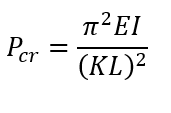
The transition between stable and unstable conditions happens at a value called " critical buckling load "( Pcr ) which can be calculated using Euler’s Formula.

Pcr = Critical Buckling load
𝐸 = Elastic Modulus
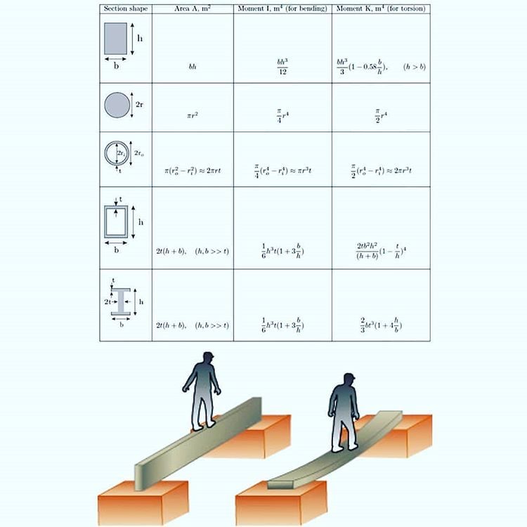
𝐼 = least second moment of area (I=bd3/12)
Stated that 𝐸 and 𝐼 are material constants, the linear relationship between the length and critical load can be found.
Stable, Unstable and Neutral Equilibrium
Stable Equilibrium ( 0 < P < Pcr )
When an axial load is less than the critical load and the geometry of the strut is straight 𝜃=0.

Unstable Equilibrium (P > Pcr )
When an axial load is greater than the critical load. Nevertheless, the structure is still in equilibrium if the angle is kept to 0 degrees (𝜃 = 0). However, the strut is unstable and cannot maintain its stability therefore by the slightest disturbance, the strut will buckle and fail.

Neutral Equilibrium (P = Pcr )
When an axial load is equal to the critical load the strut is neither stable nor unstable, it is at the peak of stability and instability. That been said the structure can handle small angles without buckling.

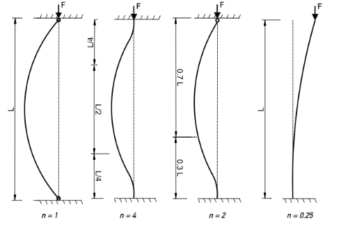
Different Support Reactions Effects
The conditions of the support reactions influence the buckling of a material. As shown above, the effective length is at a maximum (2L) when there are no support reactions placed to the strut. Therefore, we can evaluate that the number of support reactions has a relationship to the buckling displacement of the strut.
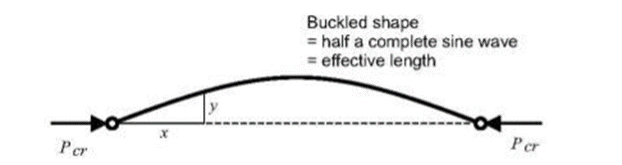
Buckling due to compression can be observed by comparing it to the sin curve elongations. The strut tends to buckle in the centre of its length. By looking at the data collected in a laboratory test the theoretical buckling load is higher than the experimental and this is due to the material imperfection but also due to the different support reactions that can create different displacement of the strut (buckling).
Essential Books for Civil Engineering Students
SI reccomended

Are you a student? Join the SI Platform now
Submit your work 📝 and get featured 📌 on our website 💥
A conclusion for your Lab Report
To conclude, the experiment showed the linearity between load and length . The data obtained indicate that the longer struts were experiencing a lower buckling load than the shorter struts. Both of them had the same material properties so due to the length of the strut the buckling values vary.
Linear elastic behaviour is shown of the material as the graph logP vs logL is plotted. The evaluation is that by decreasing length and increasing the cross-section of the strunt, critical buckling load is higher making the material to resist to buckling at higher loads applied. A linear relationship is shown on the graph

You May Also Find Useful:
The difference between buckling, compression & shear.

Tension is about pulling and compression is about pushing, then shear is about sliding. When lateral bending occurs, we can say that the column has experienced buckling.
Read More...
- Engineering
Recent Posts
The Role of ICE Attributes in the Digital Transformation of the Future Digital Civil Engineer
Characteristics of Strength in Concrete and Steel Structures
Revolutionizing Construction Process with MEP BIM Coordination
Buckling of Struts
Cite this chapter.

- D. W. A. Rees 2
254 Accesses
Euler’s theory predicts the axial compressive force required to initiate bucking in a long thin strut. Ideally, a perfectly straight strut, when subjected to a purely compressive load, would compress and not buckle. Buckling is therefore the result of imperfections that prevent the load from being applied perfectly axially; e.g. from eccentric loading and lack of initial straightness. The combined effects of these imperfections on overall buckling behaviour is predictable when long struts are to operate under elastic conditions. We need only derive an instability criterion from the lateral deflection that occurs. This approach is attributed to Leonhard Euler (1707–83). It can be applied to long struts with the following end fixings.
This is a preview of subscription content, log in via an institution to check access.
Access this chapter
Institutional subscriptions
Unable to display preview. Download preview PDF.
Author information
Authors and affiliations.
Department of Manufacturing and Engineering Systems, Brunel University, UK
D. W. A. Rees
You can also search for this author in PubMed Google Scholar
Copyright information
© 1997 D.W.A. Rees
About this chapter
Rees, D.W.A. (1997). Buckling of Struts. In: Basic Solid Mechanics. Palgrave, London. https://doi.org/10.1007/978-1-349-14161-6_8
Download citation
DOI : https://doi.org/10.1007/978-1-349-14161-6_8
Publisher Name : Palgrave, London
Print ISBN : 978-0-333-66609-8
Online ISBN : 978-1-349-14161-6
eBook Packages : Engineering Engineering (R0)
Share this chapter
Anyone you share the following link with will be able to read this content:
Sorry, a shareable link is not currently available for this article.
Provided by the Springer Nature SharedIt content-sharing initiative
- Publish with us
Policies and ethics
- Find a journal
- Track your research
Join TheConstructor to ask questions, answer questions, write articles, and connect with other people. When you join you get additional benefits.
Confirm Password *
First Name *
Last Name *
Country Select a country… Åland Islands Afghanistan Albania Algeria Andorra Angola Anguilla Antarctica Antigua and Barbuda Argentina Armenia Aruba Australia Austria Azerbaijan Bahamas Bahrain Bangladesh Barbados Belarus Belau Belgium Belize Benin Bermuda Bhutan Bolivia Bonaire, Saint Eustatius and Saba Bosnia and Herzegovina Botswana Bouvet Island Brazil British Indian Ocean Territory British Virgin Islands Brunei Bulgaria Burkina Faso Burundi Cambodia Cameroon Canada Cape Verde Cayman Islands Central African Republic Chad Chile China Christmas Island Cocos (Keeling) Islands Colombia Comoros Congo (Brazzaville) Congo (Kinshasa) Cook Islands Costa Rica Croatia Cuba CuraÇao Cyprus Czech Republic Denmark Djibouti Dominica Dominican Republic Ecuador Egypt El Salvador Equatorial Guinea Eritrea Estonia Ethiopia Falkland Islands Faroe Islands Fiji Finland France French Guiana French Polynesia French Southern Territories Gabon Gambia Georgia Germany Ghana Gibraltar Greece Greenland Grenada Guadeloupe Guatemala Guernsey Guinea Guinea-Bissau Guyana Haiti Heard Island and McDonald Islands Honduras Hong Kong Hungary Iceland India Indonesia Iran Iraq Isle of Man Israel Italy Ivory Coast Jamaica Japan Jersey Jordan Kazakhstan Kenya Kiribati Kuwait Kyrgyzstan Laos Latvia Lebanon Lesotho Liberia Libya Liechtenstein Lithuania Luxembourg Macao S.A.R., China Macedonia Madagascar Malawi Malaysia Maldives Mali Malta Marshall Islands Martinique Mauritania Mauritius Mayotte Mexico Micronesia Moldova Monaco Mongolia Montenegro Montserrat Morocco Mozambique Myanmar Namibia Nauru Nepal Netherlands Netherlands Antilles New Caledonia New Zealand Nicaragua Niger Nigeria Niue Norfolk Island North Korea Norway Oman Pakistan Palestinian Territory Panama Papua New Guinea Paraguay Peru Philippines Pitcairn Poland Portugal Qatar Republic of Ireland Reunion Romania Russia Rwanda São Tomé and Príncipe Saint Barthélemy Saint Helena Saint Kitts and Nevis Saint Lucia Saint Martin (Dutch part) Saint Martin (French part) Saint Pierre and Miquelon Saint Vincent and the Grenadines San Marino Saudi Arabia Senegal Serbia Seychelles Sierra Leone Singapore Slovakia Slovenia Solomon Islands Somalia South Africa South Georgia/Sandwich Islands South Korea South Sudan Spain Sri Lanka Sudan Suriname Svalbard and Jan Mayen Swaziland Sweden Switzerland Syria Taiwan Tajikistan Tanzania Thailand Timor-Leste Togo Tokelau Tonga Trinidad and Tobago Tunisia Turkey Turkmenistan Turks and Caicos Islands Tuvalu Uganda Ukraine United Arab Emirates United Kingdom (UK) United States (US) Uruguay Uzbekistan Vanuatu Vatican Venezuela Vietnam Wallis and Futuna Western Sahara Western Samoa Yemen Zambia Zimbabwe
By registering, you agree to the Terms of Service and Privacy Policy . *
Log in to TheConstructor to ask questions, answer people’s questions, write articles & connect with other people. When you join you get additional benefits.
Join for free or log in to continue reading...
Username or email *
Forgot Password
Lost your password? Please enter your email address. You will receive a link and will create a new password via email.
Sorry, you do not have a permission to ask a question, You must login to ask question. Get the paid membership
theconstructor.org
Strut test to determine euler’s buckling load of strut.
Do you need to remove the ads? Get the paid membership
🕑 Reading time: 1 minute
Strut test is used to determine the Euler's buckling load of the strut. Struts are long, slender columns that fail by buckling some time before the yield stress in compression is reached.
The Euler's buckling load is a critical load value that forces the strut to bend suddenly to one side and buckle before achieving the acceptable compressive strain. At the point of failure, the actual compressive stress at the point of failure can be less than the ultimate compressive strength.
The buckling occurs due to imperfections in the straightness of the strut, the applied load is not along the axis of the strut, and one part of the material may yield in compression more readily than others owing to some lack of uniformity in the material properties throughout the strut.
Strut testing apparatus, which is designed to carry out tests on struts of various lengths, with ends either hinged or fixed, is employed to determine the Euler's buckling load of a strut.
Theory and Principle
In the case of very long columns, the failure happens mainly due to bending. The Euler's relations give the crippling load for long columns for various end condition:

E: Modulus of Elasticity of the material (2.1 x 10 5 N/mm 2 )
I: Moment of Inertia of the cross Section of the strut (mm 4 )
L: Effective length of the strut which is equal to total length of the strut (L) when both ends are hinged, 0.5L when the ends are fixed, L/(2)^0.5 when one end fixed and other end hinged, and 2L when one end fixed and the other end is free.
- Strut Testing Apparatus
- Venire Caliper Scale

Strut Test Procedure
- Clean the strut with sandpaper.
- Adjust the rope slide to suit the length of the strut and place the strut between the top and bottom adapter.
- For tests with hinged end, two balls are provided which should be tightened properly to ensure end fixity.
- Move the side sliding block so that the micrometer strut is approximately against the midpoint of the length of the strut and clamp it firmly.
- Now adjust the micrometer Sliding holder, so that the micrometer comes exactly at the midpoint of the strut.
- Place the weight hanger over the top socket such that the loading is purely axial.
- Put the switch `on' so that whenever the micrometer touches the strut the indicator lamp glows.
- Carefully rotating the strut with fingers through one revolution, the maximum and minimum readings of the micrometer are noted. The purpose of this is to determine the direction of curvature of the strut and also to get the amount of initial curvature.
- The strut has to be placed such that the initial curvature is away from the micrometer side. First, determine the initial reading of the micrometer with the initial curvature away from the micrometer.
- Then add weights (in step of l kg) load on both sides of the hanger so that the strut bends in the direction away from the micrometer and note the reading.
- The difference between the two readings gives the actual deflection due to the weights now added. Do not rotate the strut while adding loads since the strut has to be kept such that the curvature is pointing the same direction always.
Plot a graph of load (P) versus the total deflection of the strut when a particular load is applied (Delta).

Calculation
Use Euler's formula for the computation of the buckling load of a strut. The equation is provided above which is equation 1.
1. By Eulers formula = ___________N
2. Experimental Values= _________N
Also Read : Basic Concepts of Stability of Structure

Madeh Izat Hamakareem
Related posts.

Specifications of Brickwork in Superstructure

Backfilling in Foundation : Types and Procedure
Login to your account
Change password, your password must have 8 characters or more and contain 3 of the following:.
- a lower case character,
- an upper case character,
- a special character
Password Changed Successfully
Your password has been changed
Create a new account
Can't sign in? Forgot your password?
Enter your email address below and we will send you the reset instructions
If the address matches an existing account you will receive an email with instructions to reset your password
Request Username
Can't sign in? Forgot your username?
Enter your email address below and we will send you your username
If the address matches an existing account you will receive an email with instructions to retrieve your username
- Institutional Access
Cookies Notification
Our site uses javascript to enchance its usability. you can disable your ad blocker or whitelist our website www.worldscientific.com to view the full content., select your blocker:, adblock plus instructions.
- Click the AdBlock Plus icon in the extension bar
- Click the blue power button
- Click refresh
Adblock Instructions
- Click the AdBlock icon
- Click "Don't run on pages on this site"
uBlock Origin Instructions
- Click on the uBlock Origin icon in the extension bar
- Click on the big, blue power button
- Refresh the web page
uBlock Instructions
- Click on the uBlock icon in the extension bar
Adguard Instructions
- Click on the Adguard icon in the extension bar
- Click on the toggle next to the "Protection on this website" text
Brave Instructions
- Click on the orange lion icon to the right of the address bar
- Click the toggle on the top right, shifting from "Up" to "Down
Adremover Instructions
- Click on the AdRemover icon in the extension bar
- Click the "Don’t run on pages on this domain" button
- Click "Exclude"
Adblock Genesis Instructions
- Click on the Adblock Genesis icon in the extension bar
- Click on the button that says "Whitelist Website"
Super Adblocker Instructions
- Click on the Super Adblocker icon in the extension bar
- Click on the "Don’t run on pages on this domain" button
- Click the "Exclude" button on the pop-up
Ultrablock Instructions
- Click on the UltraBlock icon in the extension bar
- Click on the "Disable UltraBlock for ‘domain name here’" button
Ad Aware Instructions
- Click on the AdAware icon in the extension bar
- Click on the large orange power button
Ghostery Instructions
- Click on the Ghostery icon in the extension bar
- Click on the "Trust Site" button
Firefox Tracking Protection Instructions
- Click on the shield icon on the left side of the address bar
- Click on the toggle that says "Enhanced Tracking protection is ON for this site"
Duck Duck Go Instructions
- Click on the DuckDuckGo icon in the extension bar
- Click on the toggle next to the words "Site Privacy Protection"
Privacy Badger Instructions
- Click on the Privacy Badger icon in the extension bar
- Click on the button that says "Disable Privacy Badger for this site"
Disconnect Instructions
- Click on the Disconnect icon in the extension bar
- Click the button that says "Whitelist Site"
Opera Instructions
- Click on the blue shield icon on the right side of the address bar
- Click the toggle next to "Ads are blocked on this site"
System Upgrade on Tue, May 28th, 2024 at 2am (EDT)
Chapter 8: buckling of struts.
There are many forms of structural buckling. The most common form considered here is the flexural lateral buckling which occurs in slender struts under axial compression. The Euler mathematical theory of elastic buckling provides the buckling load but is idealised in that it does not limit the material's stress. Strictly, this theory can only be applied reliably to long thin members that are prone to buckling under low elastic stress levels. The stress increases for shorter struts to a theoretical cut off at the yield stress where direct compression influences the flexural buckling load. Here a number of empirical formulae are available to estimate buckling loads for so-called imperfect struts, the bases for these being a stress summation from these two causes. The Euler theory may be also be modified in a similar manner to provide useful accounts of initial imperfections including eccentric loading, lack of initial straightness and the presence of lateral loading in addition to axial compression. Various standards provide formulae restricted to shorter struts or for applications extending over a wider range from short to medium-length struts. A degree of safety is usually admitted in which Euler's theory is recognised as providing a reliable upper limit to the buckling load for long struts.
Recommended

Engineering Cheat Sheet
Column and Panel Buckling
Buckling is a physical occurrence observed in slender structures, such as columns, beams, rods or panel; when it undergoes bending due to applied loads, leading to eventual buckling. This phenomenon can result in the complete failure of the structure. Buckling occurs when the applied load surpasses the structure’s buckling load, which represents the maximum load the structure can bear before undergoing buckling. The buckling load is influenced by factors like the geometry and material composition of the structure.
Why is buckling important in engineering
Buckling is the sudden change in the shape of a part like a rod/column or structural member. A bar or column can be subject to a buckling failure mode when an axial load is applied to it in compression. The behavior of a column can be predicted based on the end condition of the column such as the bowing (sinusoidal deformation) of a column under compression.
Euler’s Buckling Formula
Euler’s Buckling Formula, a cornerstone in structural engineering, addresses the critical buckling load of slender structural member under compressive loads. Developed by Swiss mathematician Leonhard Euler in the 18th century, the formula mathematically characterizes the stability limits of a structural member based on its length, material properties, and end conditions. Expressing the critical buckling load as a function of these factors, Euler’s formula provides valuable insights into the potential for structural instability. Engineers widely apply it to design resilient structures, ensuring columns can withstand compressive forces without succumbing to buckling, thereby enhancing the stability and safety of various architectural and engineering applications.
Euler’s Buckling Formula provides an analytical expression for the critical buckling load ( P critical ) of an idealized slender column under an axial compressive load. The formula is given by:

- E is the modulus of elasticity of the material,
- I is the column’s moment of inertia ,
- L is the effective length of the column,
- K is the column effective length factor (dependent on the end conditions).
Euler’s Buckling Formula helps engineers assess the stability of columns and design structures to prevent buckling under compressive loads.
How does the moment of Inertia affect buckling?
Moment of inertia is dependent on the mass distribution of the body, the larger the moment of inertia the greater the required torque to change the body’s rate of rotation. As a result, the column is always going to buckle about the minimum axis of the moment of inertia .
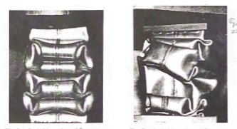
What factors affect buckling?
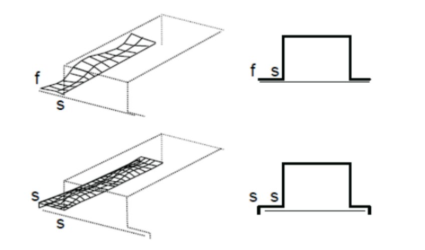
There are various factors that will affect how and when a column will buckle. Some of the most important factors are the slender ratio, loading, and boundary conditions of a column. However, it is also important to remember that material and geometry (cross-section type) also play an important role in how a part will bucket. The pictures below show the buckling behavior of two identical box columns. The picture on the left is the box column where the critical stress was greater than the yield stress of the material. As a result, the mode of failure was governed by the material. The picture on the right had a yield stress greater than the critical stress of the material. As a result, the failure was governed by the geometry of the box column.
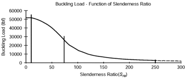
What is slenderness ratio?
The slenderness ratio in structural engineering is a crucial parameter that assesses the slender nature of a column or structural member. It is defined as the ratio of the effective length (L) of the member to its radius of gyration (r), representing how slender or squat the member is relative to its ability to resist buckling. Mathematically expressed as (Slenderness Ratio = L/r), this ratio is instrumental in determining the critical buckling load and assessing the stability of the structure under compressive loads. A higher slenderness ratio indicates greater susceptibility to buckling, when the slenderness ratio exceeds a value of 100 for a strong slim column, failure by buckling can be expected. Columns of stiffer and more brittle materials will buckle at lower slenderness ratios.
Effective length and end conditions in engineering buckling
Effective length and end conditions play pivotal roles in the engineering analysis of buckling, influencing the stability of structural elements like columns. The effective length (L) represents the hypothetical length of a column that would buckle under the same conditions as the real column. The effective length is multiplied by the actual length of the column to obtain a value that represents the column’s behavior with respect to buckling.
Effect lenth takes into consideration the end conditions, which dictate how a column is restrained at its ends. Common end conditions include pinned ends and fixed ends, each influencing the column’s behavior. Engineers use effective length and end conditions to calculate the critical buckling load, guiding the design process to enhance structural stability and prevent premature failure under compressive loads.
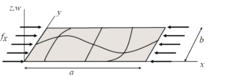
What is panel buckling?
Plates are initially flat structural elements, with a very small thickness compared with the remaining dimensions. The buckling of a panel or plate is often referred to as wrinkling and it is the result of the shear stress which is caused by compression load. The buckling behavior of panels is very different when compared to the behavior of columns.
Is buckling a sudden failure?
For the vast majority of cases when a structural element experiences buckling, it is a sure sign of part failure. However, it is very important to remember that the post-buckling behavior of a plate varies significantly when compared to a beam or column.
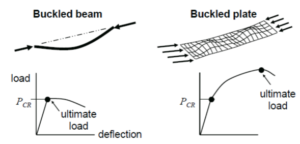
For example, once a structural beam experiences buckling, the beam will lose its ability to carry loads. This can be seen in the graph on the left where after the critical load (P cr ) is reached the load starts to drop off. However, the behavior of a plate is not the same. Even after a plate buckles it will still be able to carry an increased load.
Tools for Determining Buckling Loads
Various tools are accessible for determining the critical buckling load, including hand calculation /spreadsheets, tables, and Finite Element Analysis ( FEA ) software. Spreadsheets offer simplicity but lack customization, making them less adaptable to unique projects. Tables, like those in the back of many college textbooks, are cost-effective and widely used for calculating effective lengths that modify critical load calculations. Finite Element Analysis software, exemplified by Solidworks, Abaqus, or Altair HyperWorks proves beneficial for complex geometries or systems with irregularities. Unlike Euler’s calculation, it efficiently addresses variations in stiffness along a beam’s length due to changing cross-sections. Users can create spreadsheets, obtain tables from references, and utilize FEA software for accurate and efficient buckling load analyses.
How to Prevent Buckling?
Preventing buckling necessitates a comprehensive grasp of the structure’s buckling behavior, and one approach is to perform buckling analysis. This analysis entails determining the critical buckling load, which is the load necessary for the structure to undergo buckling. Various methods, including analytical, numerical, and experimental approaches, can be employed for buckling analysis, with the selection dependent on the problem’s complexity and the desired accuracy. Another strategy to avert buckling involves designing the structure with a buckling safety factor. This safety factor is applied to the buckling load to guarantee the structure’s ability to withstand the load without succumbing to buckling.
Design Changes to Prevent Buckling
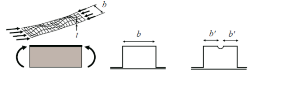
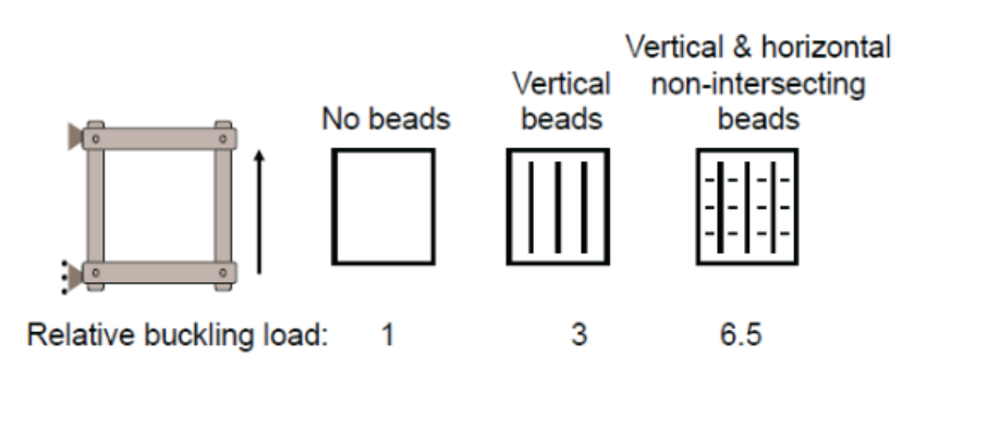
There are various design changes which can be implmented to prevent buckling from occurring. For starters looking at changing the crossectional area or slender ratio of a part which will help reduce the likelihood of bucking. Changing material will also help reduce buckling but only if critical stress was greater than the yield stress. If you are dealing with a plate/panel as shown below you can try adding stiffening beads to reduce the length of b.
As seen below by adding a fore-aft stiffening bead to a large panel you can triple the buckling load. And if you had vertical and horizontal stiffening beads which are non-intersecting you can increase the buckling load by 6.5 times. The reason why stiffening beads are able to improve buckling is because of all the added form being introduced into the panel.
What is a flange in sheet metal?
A flange is a feature commonly added to sheet metal parts that consist of bending the ends of the part at 90 degrees. Curl flanges are a great way of adding strength to a plate which also helps reduce buckling in sheet metal parts.
How the buckling test is done?
- Standard set of different materials and cross-section struts.
- VDAS Hardware and Software
- Load Meter end
- Knife-edge support
- Loading end with hand wheel
- Loading measuring end
- Deflection Indicator
Procedures:
- To begin this experiment first find the 600mm steel strut and measure the width and thickness of the beam.
- Connect the switch on the load display, tap the load measuring end to remove any effects of friction, and zero out the screen.
- Turn the hand wheel to give a small gap behind the chuck.
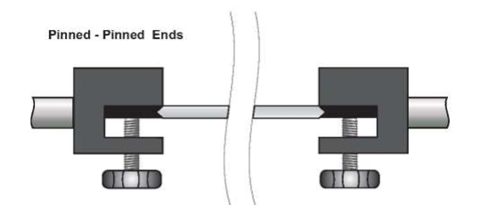
- Using the Alan key wrench loosen up the screws on the loading end and adjust it until the strut fits into each chuck with the pinned-pinned support. See figure 1: Pinned – Pinned supports
5. Move the deflection indicator to the midway point of the strut, and then zero out the deflection indicator.
6. Create a results table in the VDAS software.
7. Start to turn the hand wheel to apply a small force on the strut(less than 5N) just to ensure that the pinned ends are secure. Make sure that the beam bends away from the deflection indicator.
8. Make sure the ends of the strut are secure and the pinned end is not loose.
9. Zero the deflection indicator.
10. Move the indicator along the strut starting from the left end of the beam moving towards the right in steps of 25mm, at each step take and record data values on the software.
11. Move the deflection indicator back to the halfway point, and load the strut until the central deflection is about 6mm.
12. Repeat step 10 on the loaded beam.
13. For the second part of the experiment connect and switch on the load display. Tap the load measuring end to remove any effects of friction and zero the display.
14. Grab the 750 mm steel strut and using the calipers measure the base and height.
15. Fit the strut in the pinned-pinned end condition as above.
16. Remove the deflection indicator.
17. Use the large hand wheel to load the strut slowly until the strut buckles. As the load is being added gently press at the center and when the strut is pushed and stays in the position then you have reached the buckling point. See Figure 2: Loading of Strut.
18. Repeat steps 13-17 for the strut of lengths 650 mm and 600mm. record all data.
19. For the final part of this experiment find the 625mm steel strut (number 4) and measure its dimension ( base and height) using the calipers.
20. Repeat step 17 from the previous part of this experiment but instead of changing the length of the beam change the end conditions of the strut from pinned-pinned to pinned-fixed and fixed-fixed. Record all data. See Figure 3: End Conditions at the top of the following page.

Equations/Givens :
The theory behind this experiment is to find out at what load steel will buckle by changing the end condition and the length of the strut.
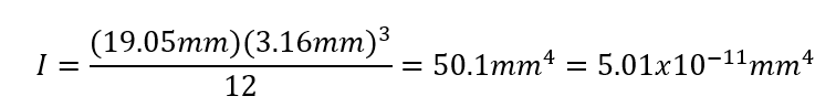
Moment of inertia :

Maximum axial buckling load:
Bending moment :
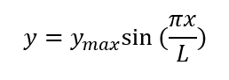
Deflection :
Published data charts:

Example calculations:
Moment of Interia:
Function approximation – f(x) = -5.86sin((2πx)/1200)
After conducting this experiment and evaluating the experimental data I am very pleased with the way everything turned out. For the first part of the experiment, a force was applied to a beam until the beam had a total deflection of 6mm at the center. The deflections at every 25mm were taken and that data was plotted against a theoretical sine wave function representing the deflection . Based on that I believe that that data came out nicely. The function that was used to represent this data theoretically was, f(x) = -5.86*sin((2πx)/1200). This equation came from the know equation for a sine wave f(x) = Asin((2πx)/λ) where A is the amplitude of the function in this our experiment the max deflection recorded was 5.86 mm and where λ represents the period of the function. Because we plotted half a sine wave function with a total distance of 600mm then the total period of the function had to be twice the distance recorded or 1200mm. unfortunately, because excel does not have the capacity to compare trigonometric functions for the correlation of the experimental curve to the actual curve I was not able to find the R 2 value.
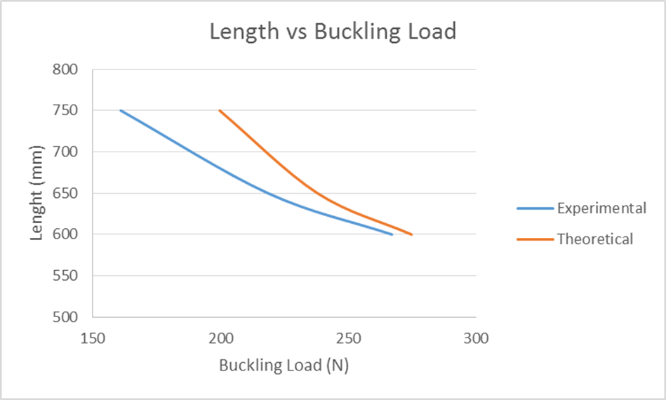
For the second part of the experiment, buckling loads were recorded as the length of the strut was changed. As expected the longer the beam is the lower the load that it can take before it buckles. The relationship between the length and the load seems to be an inverse linear function. For the most part, the data acquired was good with the highest % error at 19% error. I noticed that as the beam length increased, the % error increased. The first two measurement values have % errors of 2.8-8.1% error.
Finally for the final part of this experiment the end conditions were changed. What was noticed during this was that theoretically the fixed end should be 4 times as strong as having a pinned end. And when you used the equation that is the information that you find but in reality that is not what was measured. The fixed-fixed end conditions were only 1.8 times stronger than the pinned-pinned end conditions. I believe some of this error could have been that when the buckling occurred the harder lash back of the beam could have possibly loosed up the chucks causing an error in the forced measurement. The % error for this experiment ranged from 2%-56% error with fixed-fixed end support having the highest % error.
References:
Experiment #9 Buckling of Columns, Mechanical Measurements, Laboratory Procedure, Department of Mechanical Engineering Widener University
How useful was this post?
Click on a star to rate it!
Average rating 0 / 5. Vote count: 0
No votes so far! Be the first to rate this post.
We are sorry that this post was not useful for you!
Let us improve this post!
Tell us how we can improve this post?
Similar Posts

Mechanics of Materials 8th Edition Problem – 1.8
Determine the resultant internal loadings on the cross section through point C. Assume the reactions at the supports A and B are vertical. Sample problems and notes are based on the following textbook: Mechanics of Materials 8th Edition ISBN-13: 978-0136022305 ISBN-10: 0136022308 Edition: 7 Author: Russell C. Hibbeler Published Date: 2010 How useful was this post? Click…

Mechanics of Materials 8th Edition Problem – 1.2
Determine the resultant internal torque acting on the cross sections through points C and D. The support bearings at A and B allow free turning of the shaft. Sample problems and notes are based on the following text book: Mechanics of Materials 8th Edition ISBN-13: 978-0136022305 ISBN-10: 0136022308 Edition: 7 Author: Russell C. Hibbeler Published Date: 2010…

Mechanics of Materials 8th Edition Problem – 1.10
The boom DF of the jib crane and the column DE have a uniform weight of 50 lb/ft. If the hoist and load weigh 300 lb, determine the resultant internal loadings in the crane on cross sections through points A, B, and C. Equations of Equilibrium: For point A Equations of Equilibrium: For point B…

Automotive Suspension System 101
Have you ever wondered how an automotive suspension system is designed? From ATVs (all-terrain vehicles) to locomotives to modern passenger automobiles most types of vehicles that move people from one place to another rely on a suspension system to improve ride quality and comfort. There are a few common types of automotive suspension systems such…

How are leaf springs designed?
A leaf spring is a basic type of spring often used for suspension in vehicles. Originally known as a laminated or carriage spring, and sometimes called a semi-elliptical spring, elliptical spring, or cart spring, leaf springs are one of the oldest forms of vehicle suspension. A Leaf spring consists of one or more narrow, curved,…

Uniaxial tension test
Tension test, alternatively referred to as tensile testing or uniaxial tension test, is one of the most commonly used tests to determine important material parameters such as Young’s modulus, yield strength, ultimate strength, elongation at break, Poisson’s ratio, and Lankford coefficients (R-values). Tension testing constitutes a foundational test in materials science and engineering, involving the…
Green Mechanic
Knowledge Is Free
Buckling of Strut Lab Report
In construction applications a column or strut is an element that is used to withstand compressive load.
Strut is similar to beam but it is used in vertical position and normally horizontal beams are placed on the columns or both ends of beams are rested on two strut s on either end of the beam.
strut s are usually designed to withstand high compressive loads and they can fail or buckle if the loads are too large and columns are unable to withstand that load.
Normally the load at which the column buckles is called critical load and strut is typically designed to be used well below this critical load.
However, even if the structure is subjected to small loading well below critical buckling load of strut , the continuous application of such loads could eventually fatigue the structure and build up to buckling failure.
Therefore, understanding the buckling of strut , its characteristics and designing in safety factors are important. In this experiment we will see how columns buckles ate different loads when their ends are fixed or pinned.
Calculating the Buckling of Strut
The following dimensions of the strut were measured for rectangular strut
Width, b = 100 mm
Depth, d = 50 mm
For rectangular shape column the second moment of area can be calculated as
Second moment of area
I =(bd^3)/12
Putting in values
Second moment of area
I = 0.05*(0.1)^3/12 = 4.16* 〖10〗^(-6) m^4
The buckling load for buckling of struct can also be calculated using Euler equation where it can be seen that the buckling
load only depends on the cross sectional area, material properties such as Young’s modulus ‘E’ and the way both ends are fixed.
The Euler equation is given by
Where the value of ‘k’ depends how the ends are fixed.
For Pin End Connection
If both ends are pinned then ‘k=1’ will be taken.
P =(3.14*97*〖10〗^9*4.16* 〖10〗^(-6))/(1*L)
For both fix end connections
P =(3.14*97*〖10〗^9*4.16* 〖10〗^(-6))/(0.5*L)
If one end is pinned and the other end is fixed then ‘k=o.7’ will be taken.
P =(3.14*97*〖10〗^9*4.16* 〖10〗^(-6))/(0.7*L)
| experimental reading for buckling of strut |
Discussion on Buckling of Strut
From the results given in table 2 it can be seen that different strut s buckle at different critical loads. The buckling depends on many factors such as the material by which the column is made of and the way by which both ends are fixed or pinned.
In this case it is assumed that all strut s have similar cross sectional areas and therefore have constant value for second moment of area. The columns made of brass and aluminum will have different values of ‘E’ but same value of second moment of area ‘I’ if the cross sectional area is same.
From table 2 readings it is clear that the strut s can take larger loads before knuckling when both ends are fixed. Same is true for aluminum and brass columns. The young’s modulus of brass is 97 G Pa while for Aluminum it is 69 MPa.
If the second moment of area is same for both strut s then the column made of brass should take larger load before buckling given that both ends are fixed for both strut s. From table 2 it is clear that the column made of brass buckles at 1129 N load while the strut made of Aluminum buckles at 783.5 N when both ends were fixed.
From Euler equation it can be seen that the buckling load will be directly proportional to the young’s modulus of the material the strut is made of. Therefore brass is more durable and can withstand higher compressive loads.
Concluding the Buckling of Strut
For strut design the maximum bending stress was calculated and also keeping in mind the safety factor the design stress was calculated. It was concluded that the material should be used with yield stress of 75 MPa for a safe design of strut .
For strut design the aluminum and brass strut were tested and it was seen that the brass strut has larger capacity to withstand compressive loads for similar cross sectional area and end fixing.
By considering the calculations given in this report more suitable columns can be designed to be used in underground construction for London underground tunnels.
No comments:
Post a comment.
IMAGES
COMMENTS
To conclude, the experiment showed the linearity between load and length. The data obtained indicate that the longer struts were experiencing a lower buckling load than the shorter struts. Both of them had the same material properties so due to the length of the strut the buckling values vary.
Over View of Buckling of Struts. Buckling of strut is an important phenomenon in engineering. In this experiment buckling of struts for different materials has been studied. Materials used in this study were aluminum, steel and brass. Ten samples of circular struts of similar diameter but of different length were taken for each material type.
Experiment Four- Bucking of Column where E is the elastic modulus, I is the moment of inertia, and L e is the effective length. The expression in Equation (4.3-1) is known as Euler's formula. The effective length depends upon the constraints imposed on the ends of the column. Figure 2 shows how the effective length
this lab.2 Equipment & MaterialsThe four specimens as shown in Figure 1 manufactured by either o. the following types of Aluminum. Select all four 4 of your specimens from the same material type and indicate thi. 1-T6ksi 10000 10000ksi 47 37The no. inal dimensions of each specimen. During your experiment you will measure the exact dimensions ...
The lateral load device consists of a rope, a pulley, a bracket and a set of weights. The pulley is clamped to one of the guide columns. The bracket holds the rod specimen and is locked in place ...
L : Length of the strut (m) Compare the theoretical and experimental values of buckling load. Experiment 2: In this experiment, buckling load of pinned-fixed end struts will be analyzed. Apply the same procedure explained in "Experiment 1", the difference is that the Euler buckling formula for pinned-fixed end struts is as follows: Pe= 2π2EI L2
Practical struts may differ from perfect Euler struts because of additional lateral loadings, eccentricities and initial curvature. The buckling behav iour of these struts can be identified with the attainment of the compress ive yield stress at the section subjected to the greatest bending moment. 8.2.1 Eccentric Load and Pinned-Ends
the strut until reaching the critical buckling load. They then repeat the experiment using different strut lengths or fixing conditions, analyzing their results. The equipment includes strut storage space and five different sizes of aluminium strut. The lecturer guide provides details of the equipment including sample experiment results.
Buckling experiment There is a critical stress at which buckling occurs depending on the material ... The steel compression strut BC of the frame ABC is a tube with an outer diameter of d = 48 mm and a wall thickness of t = 5 mm. Determine the factor of safety against elastic buckling if a
Ideally, a perfectly straight strut, when subjected to a purely compressive load, would compress and not buckle. Buckling is therefore the result of imperfections that prevent the load from being applied perfectly axially; e.g. from eccentric loading and lack of initial straightness. The combined effects of these imperfections on overall ...
Buckling is an instability which generally occurs when "thin" structures are subjected to compressive loading. In this laboratory exercise, you will study the response of a clamped-clamped column under axial compression. During the experiment the data acquisition system will monitor the displacements of the column and the load.
🕑 Reading time: 1 minute Strut test is used to determine the Euler's buckling load of the strut. Struts are long, slender columns that fail by buckling some time before the yield stress in compression is reached. The Euler's buckling load is a critical load value that forces the strut to bend suddenly to one […]
Buckling Load of as Pinned-End Strut:This guide describes how to set up and perform experiments related to the Buckling of Struts. The equipment clearly demo...
Tools. Abstract: There are many forms of structural buckling. The most common form considered here is the flexural lateral buckling which occurs in slender struts under axial compression. The Euler mathematical theory of elastic buckling provides the buckling load but is idealised in that it does not limit the material's stress. Strictly, this ...
19. For the final part of this experiment find the 625mm steel strut (number 4) and measure its dimension ( base and height) using the calipers. 20. Repeat step 17 from the previous part of this experiment but instead of changing the length of the beam change the end conditions of the strut from pinned-pinned to pinned-fixed and fixed-fixed.
Therefore, understanding the buckling of strut, its characteristics and designing in safety factors are important. In this experiment we will see how columns buckles ate different loads when their ends are fixed or pinned. Calculating the Buckling of Strut . The following dimensions of the strut were measured for rectangular strut. Width, b ...
For comparison, the length of the free-clamped column at buckling loaded by the same weight is l2 c = ˇ2 4 EI N c = 2:47 EI N c (10.13) The bottom of both column sees the same weight, but the critical length of the column undergoing self-buckling is r 7:84 2:47 = 1:78 times taller than a similar cross-section column loaded at its tip. 10-2
Description. One of a range of experiment modules that fi t to the Structures platform (STS1, available separately), this product helps students to understand the nature of buckling in slender beams that simulate 'struts'. Students fi t one of a choice of struts between the two major parts of the product. One part has a hand-operated ...
Buckling of Struts Group 7 By Nathan Golsby-Taylor @ Context Summary Introduction Theory and Equations Apparatus ... This laboratory experiment shows the that the longer strut will buckle sooner the a shorter strut. This is backed up by the amount of weight (N) the beams could hold before they buckled. Pcr (N) Difference (Exp. - Theo.) x 100 ...
In this presentation, strut buckling experiment ONLINE demonstration is shown and presented to the structural engineering learners. The procedures and its ...
226 MODULE 9. STABILITY AND BUCKLING 6.Let us introduce the following non-dimensional quantities u = a=L and = kL , and rewrite the previously found condition. Solution: With de nition u = a=L , = kL , and the ^ a = L a we just de ned above, we can get identities: ka = u and k ^a = (1 u ).
Experiment for the study of buckling of struts and the relationships between length, end fixing conditions and buckling load. ... One of a range of experiment modules that fit to the Structures platform (STS1, available separately), this product helps students to understand the nature of buckling in slender beams that simulate 'struts ...
In summary, the flexural buckling of FRP struts is related to many factors, and the influence of these factors is complicated, ... [157] observed a variety of failure modes in the global buckling experiment of multi-angle laminated CFRP circular tubes. Firstly, based on the three-dimensional elastic theory, the stress and strain fields of FRP ...